
Page 383 - Engineering Digital Design
P. 383
354 CHAPTER 8 / ARITHMETIC DEVICES AND ARITHMETIC LOGIC UNITS (ALUs)
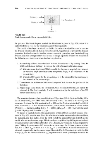
Dividend, A A/B
Parallel Remainder, R
Divisor, B m Divider
k
i
Quotient, Q
FIGURE 8.20
Block diagram symbol for an nlm parallel divider.
the quotient. The block diagram symbol for this divider is given in Fig. 8.20, where it is
understood that m < n for the binary integers of these operands.
The details of the logic circuitry for a divider depend on the algorithm used to execute
the division operation. Recall that in Subsection 2.9.5, Algorithm 2.12 presented a division
procedure that is close to the familiar subtract-and-shift procedure used in decimal long
division. It is this same procedure that is used to design a parallel divider, but modified in
the following way to accommodate hardware application:
1. Successively subtract the subtrahend B from the minuend A by starting from the
MSB end of A and shifting 1 bit toward the LSB after each subtraction stage:
(a) When the most significant (MS) borrow bit for the present stage is 0, the minuend
for the next stage (remainder from the present stage) is the difference of the
present stage.
(b) When the MS borrow for the present stage is 1, the minuend for the next stage is
the minuend of the present stage.
2. Complement the MS borrow bit for each stage and let it become the quotient bit for
that stage.
3. Repeat steps 1 and 2 until the subtrahend B has been shifted to the LSB end of the
minuend A. The final remainder R will be determined by the logic level of the MS
borrow as in step la or Ib.
The procedure just described, a modification of Algorithm 2.12, is illustrated in Fig. 8.21 a
for a 5-bit dividend, A = 10001 and a 3-bit divisor B = 011. The result is A -=- B = Q with
remainder /?, where the 3-bit quotient is Q — 101 and the 5-bit remainder is R = 00010.
Thus, in decimal 17 -^ 3 = 5 with remainder 2, which would be written as 17 and 2/3 or
17.66666 .... Similarly, in Fig. 8.21b, A = 11011 2 (27, 0), B = 100 2 (4i 0) with the result
Q = 001102 (610) and R = 00011 2 (3 10).
To design a parallel divider, the requirements of the subtract-and-shift process, illus-
trated in Fig. 8.21, must be met. First, the subtrahend must be successively subtracted from
the minuend, and then shifted from the MSB end of the minuend toward its LSB end by
one bit after each subtraction stage. This is easily accomplished by shifting the subtrahend
presentation to an array of full subtracters (FSs). Second, the remainder R must be properly
gated. Taking B OM to mean the MS borrow for a given stage, the division process requires
that R = D when B out = 0 and R = A for B out = 1, where D and A are the difference and
minuend, respectively, for the present stage. Shown in Fig. 8.22 are the truth table (a), EV
K-map (b), and the subtracter module (c), together with its block symbol (d), that meet the