
Page 387 - Engineering Digital Design
P. 387
358 CHAPTER 8 / ARITHMETIC DEVICES AND ARITHMETIC LOGIC UNITS (ALUs)
^ .
ny ny my
I I I
B A
n-bit Slice ALU
: M C fj
G P F
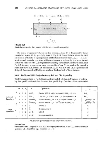
FIGURE 8.25
Block diagram symbol for a general 1-bit slice ALU with CLA capability.
The choice of operation between the two operands, A and B, is determined by the m
mode/select inputs, M, S m-2 • • • S\ SQ, shown in Fig. 8.25. The mode input M sets the ALU
for either an arithmetic or logic operation, and the function select inputs, S m _2 • •• S\ SQ, de-
termine which particular operation, within the arithmetic or logic mode, is to be performed.
Just as the carry-out bit C out is required for cascading standard R-C arithmetic units, as in
Fig. 8.5, the carry propagate and carry generate bits, P and G, are required for cascading
carry look-ahead (CLA) units. In this section, ALUs with R-C and CLA capabilities are
designed. Commercial ALU chips are available that have both of these features.
8.8.1 Dedicated ALU Design Featuring R-C and CLA Capability
The EV operation table in Fig. 8.26 represents a simple 1-bit slice ALU capable of perform-
ing four specific arithmetic functions and four specific logic functions, all on command of
F Operation*
M s, S 0 C out
1 ' 0 0 0 Aec in Transfer (LSB C in = 0) or increment (LSB C in = 1 ) of A A-C in
Arithmetic J 0 0 1 A©C in 1 's (LSB C jn = 0) or 2's (LSB C in = 1 ) complement of A A'C in
Operations j
0 1 0 A©B©C. A plus B if LSB C in = 0 or A plus B plus 1 if LSB C jn = 1 C in(A©B) + A-B
in
1 x ° 1 1 A©B©Q n B minus A if LSB C in = 1 or A plus B if LSB C in - 0 C in(A©B) + A-B
' 1 0 0 A Transfer A 0
|
Logic J 1 0 1 A Complement of A 0
Operations ]
1 1 0 A + B A ORB 0
I 1 1 1 A + B A complement OR A 0
x
* Subtraction operations assume 2's complement arithmetic.
FIGURE 8.26
Operation table for a simple 1-bit slice ALU showing output functions, F and C out, for four arithmetic
operations (M = 0) and four logic operations (M =1).