
Page 390 - Engineering Digital Design
P. 390
8.8 ARITHMETIC AND LOGIC UNITS 361
B n.,(H) A^H) B 2(H) A 2 (H) B,(H) A,(H) B 0(H) A 0(H)
1 1 . r T T ^ r I i; * ¥ ^ r
r
B A B A B A B A
1-bit 1-bit 1-bit 1-bit
OU1 « +— out oul out u* 4-
ALU Ci " ALU U h * ALU t)0 * ° ALU
F F F F
F n.,(H) F 2(H) F,(H) F 0(H)
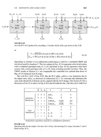
FIGURE 8.29
An n-bit R-C ALU produced by cascading n 1-bit slice ALUs of the type shown in Fig. 8.28.
or
I C out = MQ [(A 0 S 0) © (Si B)] + M(Si B}(A 0 S 0) J [ , (8.15)
1
/C D\
-
, .
l
°
-
-
depending on whether or not subfunction partitioning is used for a combined CRMT and
two-level result for function F. The two outputs in Eqs. (8.14) represent a five-level system
with a combined gate/input tally of 11/24, and those in Eqs. (8.15) represent a four-level
system with a total gate/input tally of 11/25, both excluding possible inverters. Thus, the
CRMT results in Section 5.11 are comparable but somewhat less optimal than those of
Eqs. (8.13) extracted from K-maps.
The n-bit R-C ALU of Fig. 8.29, like the R-C adder, suffers a size limitation due to
the ripple-carry effect, as discussed in Subsection 8.2.3. To overcome this limitation the
carry look-ahead (CLA) feature can be coupled with the ALU design. (See Section 8.4 for a
discussion of the CLA adder.) In Fig. 8.30 is the I/O table for the 1-bit slice ALU with CLA
M s, So F P G
[ 0 0 0 A0C m A 0
Arithmetic J 0 0 1 A0C in A A
Operations j 0 1 0 A©B0C in (A©B) A-B
I 0 1 1 A0B©C jn (A0B) A-B
v
r f 1 0 0 A 0 0
Logic J 1 0 1 A 0 0
Operations | 1 1 0 A + B 0 0
I 1 1 1 A + B 0 0
* Subtraction operations assume 2's complement arithmetic.
FIGURE 8.30
Operation table for the simple 1-bit slice ALU of Fig. 8.26 showing CLA output functions P and G
based on Eqs. (8.7).