
Page 395 - Engineering Digital Design
P. 395
366 CHAPTER 8 / ARITHMETIC DEVICES AND ARITHMETIC LOGIC UNITS (ALUs)
a given nonarithmetic operation, it follows that D = \ and C out(L) = l(L) = 0(//), which
is interpreted as a carry-out disable for that operation. Thus, the carry-out disable feature
of the PALU is equivalent to the false carry rejection used in the ALU operation tables of
Figs. 8.26 and 8.30. In a sense, the output of MUX-D performs the same mode control
operation as does M in the ALU of Figs. 8.28 and 8.29.
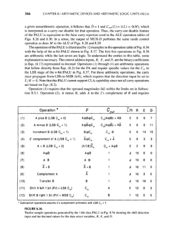
The operation of the PALU is illustrated by 12 examples in the operation table of Fig. 8.36
with the help of the n-bit PALU shown in Fig. 8.37. The first five operations in Fig. 8.36
are arithmetic while the last seven are logic. To understand the entries in this table, some
explanation is necessary. The control address inputs, R, E, and D, are the binary coefficients
in Eqs. (8.17) represented in decimal. Operations (1) through (4) are arithmetic operations
that follow directly from Eqs. (8.2) for the FA and require specific values for the C in to
the LSB stage of the n-bit PALU in Fig. 8.37. For these arithmetic operations, the carry
must propagate from LSB-to-MSB (left), which requires that the direction input be set to
L/R = 0. Note that this PALU cannot support CLA capability since not all carry operations
are based on Eqs. (8.2).
Operation (1) requires that the operand magnitudes fall within the limits set in Subsec-
tion 8.3.1. Operation (2), A minus B, adds A to the 2's complement of B and requires
Operation * F C out L/R R E D
(1) A plus B (LSB C jn = 0) A0B©C in C in(A©B) + AB 0 6 6 7
(2) A minus B (LSB C in = 1) A0BeC in C in(AeB) + AB 0 6 9 11
(3) Increment B (LSB C in = 1) Bec in C in 'B 0 6 10 15
(4) 2' complement of A (LSB C in = 1) A©C in C in + A 0 6 3 3
(5) A = B (LSB C in = 0) (A®B)C in C in + AeB 0 2 9 9
(6) A©B AeB 1 10 6 0
*
(7) A- B A -B 1 </> 10 8 0
(8) A~+B A+ B 1 t 10 11 0
(9) Complement A A 1 10 3 0
*
(10) Transfer B B 1 <{> 10 10 0
(11) Shift A left 1 bit (Fill = LSB C in) c in A 0 12 0 3
(12) Shift B right 1 bit (Fill = MSB CJ B 1 12 0 5
C in
Subtraction operations assume 2's complement arithmetic with LSB C in .= 1.
FIGURE 8.36
Twelve sample operations generated by the 1-bit slice PALU in Fig. 8.34 showing the shift direction
input and the decimal values for the data select variables, R, E, and D.