
Page 399 - Engineering Digital Design
P. 399
370 CHAPTER 8 / ARITHMETIC DEVICES AND ARITHMETIC LOGIC UNITS (ALUs)
M 0 GO A d ' C jn O C in1
Add/Sub
th
th
J J
Logic Arithmetic
B j-i Module X Module
L/R
J th
Output
Logic
I
Done, R, C outO C out1
j
i
Bj Aj F Bj., B J+1 M, M 0 GO
L/R Add/Sub
th
J 1-Bit PALU Module
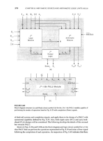
FIGURE 8.40
Block diagram structure (a) and block circuit symbol (b) for the Jth 1-bit PALU module capable of
performing the modes of operation listed in Fig. 8.39 with completion (Done) signals.
of dual-rail systems and completion signals, and apply them to the design of a PALU with
operational capability defined by Fig. 8.39. Also, both ripple-carry (R-C) and carry look-
ahead (CLA) designs will be considered. The following develops the details of this unusual
but versatile PALU.
Shown in Figs. 8.40a and 8.40b are the block diagram and logic circuit symbol for a 1-bit
slice PALU that can perform the operations represented in Fig. 8.39 and issue a Done signal
following the completion of each operation. An inspection of Fig. 8.40 indicates that there