
Page 402 - Engineering Digital Design
P. 402
8.9 DUAL-RAIL SYSTEMS AND ALUs WITH COMPLETION SIGNALS 373
Dual-rail output section
' 3 *"2 ' 1 ""0
(H) (H) (H) (H) M
I I I A GO(H)-
Aj(H) 1
4-to-1 MUX M 0 (H).
Bj(H) (Bit-wise logic section) Fj(L)
JTo Bj of Arithmetic
^ Module
UR(H) . r — Shift section
B J+,(H)
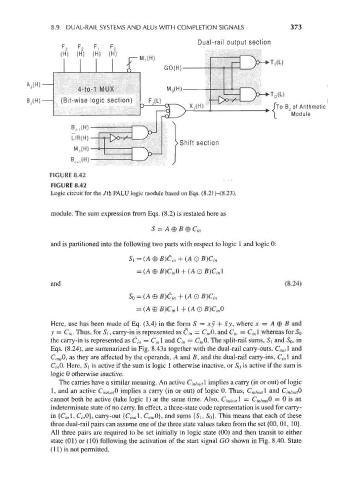
FIGURE 8.42
Logic circuit for the 7th PALU logic module based on Eqs. (8.21)-(8.23).
module. The sum expression from Eqs. (8.2) is restated here as
S = A 0 B © C in
and is partitioned into the following two parts with respect to logic 1 and logic 0:
Si = (A 0 B)C in + (AQ B)C in
= (A 0 B)C inO + (A O B)C inl
and (8.24)
SQ = (A © B)C in + (A O B)dn
= (A®B)d nl+(AQB)C inQ
Here, use has been made of Eq. (3.4) in the form 5 = xy + xy, where x = A 0 B and
y = Ci n. Thus, for Si, carry-in is represented as C/ n = C/,,0, and d,, = C in 1 whereas for So
the carry-in is represented as C in = C in\ and C in = C/,,0. The split-rail sums, Si and S 0, in
Eqs. (8.24), are summarized in Fig. 8.43a together with the dual-rail carry-outs, C outl and
C OM,0, as they are affected by the operands, A and B, and the dual-rail carry-ins, C/ nl and
C, ;,0. Here, Si is active if the sum is logic 1 otherwise inactive, or So is active if the sum is
logic 0 otherwise inactive.
The carries have a similar meaning. An active C in/ olltl implies a carry (in or out) of logic
1, and an active C/,^,0 implies a carry (in or out) of logic 0. Thus, C in/ outl and C,v owfO
cannot both be active (take logic 1) at the same time. Also, C- inj oM\ = C,v OM,0 = 0 is an
indeterminate state of no carry. In effect, a three-state code representation is used for carry-
in {C/,,1, C/,,0}, carry-out {C outl, C ou,0}, and sums (Si, S 0}. This means that each of these
three dual-rail pairs can assume one of the three state values taken from the set (00, 01, 10}.
All three pairs are required to be set initially in logic state (00) and then transit to either
state (01) or (10) following the activation of the start signal GO shown in Fig. 8.40. State
(11) is not permitted.