
Page 398 - Engineering Digital Design
P. 398
8.9 DUAL-RAIL SYSTEMS AND ALUs WITH COMPLETION SIGNALS 369
and can be represented either by the K-map in Fig. 8.38a or by the table in Fig. 8.38b.
The table is generated by asigning 1's and O's to the four coefficients, /% F2, F\, and F Q.
These functions will again be used by an even more versatile ALU, which is designed in the
following section.
8.9 DUAL-RAIL SYSTEMS AND ALUs WITH COMPLETION SIGNALS
As implied in Section 8.8, ALUs are important because they make possible the use of
the same device to perform many different operations, thereby increasing versatility while
minimizing the need to combine different modules for those operations. Because of these
advantages, ALUs are commonly found in processors where the specific operations are
performed on command from the controller in the processor. Although these ALUs support
a variety of arithmetic and logic operations and may include CLA capability, they typically
have single rail carries (like those treated in Section 8.8) and cannot communicate to the
processor when a given operation has been completed. To remedy this situation, completion
signals are issued following worst-case delays that are associated with the various ALU
operations.
This section features a programmable ALU (PALU) that will issue a final completion
(DONE) signal immediately following the completion of any operation, no matter how
complex or simple it is. This is a significant feature for an ALU, since arithmetic op-
erations require more time to complete (because of the carry problem) than do bitwise
logic operations. Used in a microprocessor, PALUs with DONE signals avoid the need
to assign worst-case delays to the various ALU operations. Thus, whenever an operation
(logic or arithmetic) is completed, a DONE signal is sent to the CPU (central process-
ing unit), thereby permitting immediate execution of the next process without unnecessary
delay.
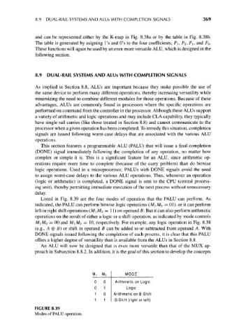
Listed in Fig. 8.39 are the four modes of operation that the PALU can perform. As
indicated, the PALU can perform bitwise logic operations (M\ MQ = 01), or it can perform
left or right shift operations (M[Mo = 11) on operand B. But it can also perform arithmetic
operations on the result of either a logic or a shift operation, as indicated by mode controls
MI MO = 00 and MI MO = 10, respectively. For example, any logic operation in Fig. 8.38
(e.g., A 0 B) or shift in operand B can be added to or subtracted from operand A. With
DONE signals issued following the completion of each process, it is clear that this PALU
offers a higher degree of versatility than is available from the ALUs in Section 8.8.
An ALU will now be designed that is even more versatile than that of the MUX ap-
proach in Subsection 8.8.2. In addition, it is the goal of this section to develop the concepts
M, M 0 MODE
0 0 Arithmetic on Logic
0 1 Logic
1 0 Arithmetic on B-Shift
1 1 B-Shift (right or left)
FIGURE 8.39
Modes of PALU operation.