
Page 403 - Engineering Digital Design
P. 403
374 CHAPTER 8 / ARITHMETIC DEVICES AND ARITHMETIC LOGIC UNITS (ALUs)
\B \B
A\ 0 1 A\ 0 1
0 C. 1 C 0 0 C iM0 C 1
in in in
1 c o 1 cj c, o
A B C out 1 C ou.° s, S o in CJ n
0 0 0 1 C in1 c o \B /b 1 \B /
in
0 1 CJ c o clo C in 1 A\ 0 1 A\ 0 1
in
1 0 C. 1 c o c.o C 1
in in in in in 0 0 CJ 0 1 c.o
1 1 1 0 C. 1 c. o
1 CJ 1 1 c o 0
in
(a) (b)
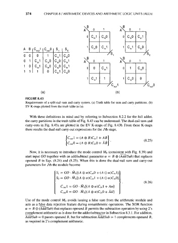
FIGURE 8.43
Requirements of a split-rail sum and carry system, (a) Truth table for sum and carry partitions, (b)
EV K-maps plotted from the truth table in (a).
With these definitions in mind and by referring to Subsection 8.2.2 for the full adder,
the carry partitions in the truth table of Fig. 8.43 can be understood. The dual-rail sum and
carry-outs in Fig. 8.43a are plotted in the EV K-maps of Fig. 8.43b. From these K-maps
there results the dual-rail carry-out expressions for the /th stage,
\C out\ = (A © B)C inl + AB\
Now, it is necessary to introduce the mode control MQ (consistent with Fig. 8.39) and
start input GO together with an add/subtract parameter a = B © (Add/Sub) that replaces
operand B in Eqs. (8.24) and (8.25). When this is done the dual-rail sum and carry-out
parameters for /th the module become
Si = GO • M 0[(A © a)C inO + (AQ a)C inl]
S 0 = GO- M 0[(A © aXV + (A 0 a)C inO]
(8.26)
C OM\ = GO • MQ[(A © a)Cin 1 + Aa]
C outO = GO • M 0[(A © a)C inO + Aa]
Use of the mode control MQ avoids issuing a false sum from the arithmetic module and
acts as a false data rejection feature during nonarithmetic operations. The XOR function
a = B © (Add/Sub) that replaces operand B permits the subtraction operation by using 2's
complement arithmetic as is done for the adder/subtractor in Subsection 8.3.1. For addition,
Add/Sub = 0 passes operand B, but for subtraction Add/Sub = 1 complements operand B,
as required in 2's complement arithmetic.