
Page 404 - Engineering Digital Design
P. 404
8.9 DUAL-RAIL SYSTEMS AND ALUs WITH COMPLETION SIGNALS 375
Dual-rail carry-out
logic
Aj(H)
AdaYSub(H)
Bj(H)
From Logic
Module in Completion and result logic
Figure 8.43
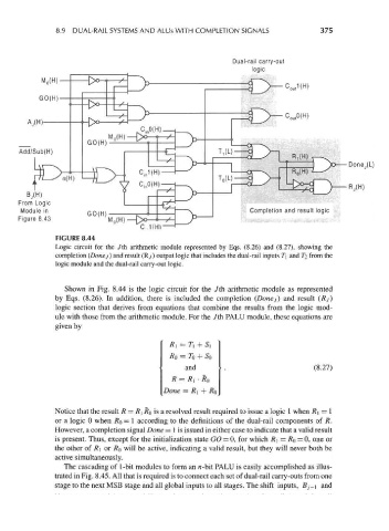
FIGURE 8.44
Logic circuit for the 7th arithmetic module represented by Eqs. (8.26) and (8.27), showing the
completion (Donej) and result (Ry) output logic that includes the dual-rail inputs T\ and TI from the
logic module and the dual-rail carry-out logic.
Shown in Fig. 8.44 is the logic circuit for the 7th arithmetic module as represented
by Eqs. (8.26). In addition, there is included the completion (Donej) and result (Rj)
logic section that derives from equations that combine the results from the logic mod-
ule with those from the arithmetic module. For the 7th PALU module, these equations are
given by
RI = T\ + 5]
RQ = TQ + So
and (8.27)
R = R] • RQ
Done = RI + R 0
Notice that the result R — R\ RQ is a resolved result required to issue a logic 1 when R\ = 1
or a logic 0 when RQ = 1 according to the definitions of the dual-rail components of R.
However, a completion signal Done = 1 is issued in either case to indicate that a valid result
is present. Thus, except for the initialization state GO = 0, for which R\ = RQ = 0, one or
the other of R\ or RQ will be active, indicating a valid result, but they will never both be
active simultaneously.
The cascading of 1-bit modules to form an n-bit PALU is easily accomplished as illus-
trated in Fig. 8.45. All that is required is to connect each set of dual-rail carry-outs from one
stage to the next MSB stage and all global inputs to all stages. The shift inputs, Bj-\ and