
Page 409 - Engineering Digital Design
P. 409
8.9 DUAL-RAIL SYSTEMS AND ALUs WITH COMPLETION SIGNALS 379
G,(L)
£ 1 C, n O(H)-
i C Ri(H)
GO(H)
Aj(H)
C KM) ^
Add/Sub(H) li "X
-A5~X P(H)
1 V-P'(H)
Bj(H) from logic
module ^ C, n1(H) .
? i7
IYI /|_|\ fXo s ~N £ 1
N N 1 R 0(H)
^ • r —^ ISo-yt.
GO(H) ." i—
v y c ino(H) — •
G (L)
° (a)
G, B A M 0 GO
Add/Sub R,(H) ~_ J^O-Donej .(L)
th
J 1-Bit
Arithmetic CLA
in1
Module
C
inO
R 1 R 0
Completion/Result logic
T
(b) (c)
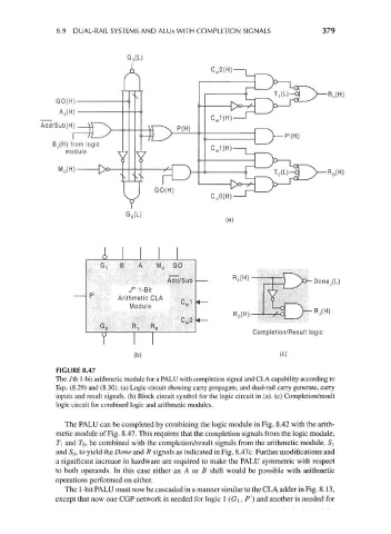
FIGURE 8.47
The Jth 1-bit arithmetic module for a PALU with completion signal and CLA capability according to
Eqs. (8.29) and (8.30). (a) Logic circuit showing carry propagate, and dual-rail carry generate, carry
inputs and result signals, (b) Block circuit symbol for the logic circuit in (a), (c) Completion/result
logic circuit for combined logic and arithmetic modules.
The PALU can be completed by combining the logic module in Fig. 8.42 with the arith-
metic module of Fig. 8.47. This requires that the completion signals from the logic module,
T\ and TQ, be combined with the completion/result signals from the arithmetic module, Si
and So, to yield the Done and R signals as indicated in Fig. 8.47c. Further modifications and
a significant increase in hardware are required to make the PALU symmetric with respect
to both operands. In this case either an A or B shift would be possible with arithmetic
operations performed on either.
The 1-bit PALU must now be cascaded in a manner similar to the CLA adder in Fig. 8.13,
except that now one CGP network is needed for logic 1 (G\ , P'} and another is needed for