
Page 411 - Engineering Digital Design
P. 411
8.10 VHDL DESCRIPTION OF ARITHMETIC DEVICES 381
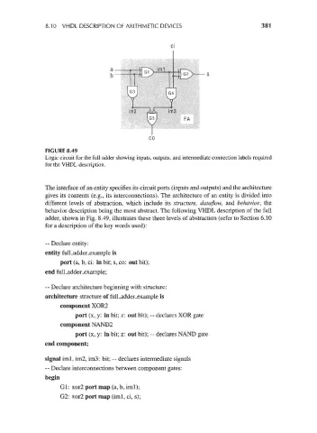
FIGURE 8.49
Logic circuit for the full adder showing inputs, outputs, and intermediate connection labels required
for the VHDL description.
The interface of an entity specifies its circuit ports (inputs and outputs) and the architecture
gives its contents (e.g., its interconnections). The architecture of an entity is divided into
different levels of abstraction, which include its structure, dataflow, and behavior, the
behavior description being the most abstract. The following VHDL description of the full
adder, shown in Fig. 8.49, illustrates these three levels of abstraction (refer to Section 6.10
for a description of the key words used):
-- Declare entity:
entity fulLadder_example is
port (a, b, ci: in bit; s, co: out bit);
end full_adder_example;
-- Declare architecture beginning with structure:
architecture structure of full_adder_example is
component XOR2
port (x, y: in bit; z: out bit); — declares XOR gate
component NAND2
port (x, y: in bit; z: out bit); -- declares NAND gate
end component;
signal iml, im2, im3: bit; -- declares intermediate signals
-- Declare interconnections between component gates:
begin
Gl: xor2 port map (a, b, iml);
G2: xor2 port map (iml, ci, s);