
Page 416 - Engineering Digital Design
P. 416
386 CHAPTER 8 / ARITHMETIC DEVICES AND ARITHMETIC LOGIC UNITS (ALUs)
8.8 Without working too hard, use four full adders (nothing else) to design a circuit that
will convert XS3 to BCD. Assume that all inputs and outputs are active high. (Hint:
Use 2's complement arithmetic.)
8.9 Analyze the adder/subtractor in Fig. 8.9 in 4 bits by adding or subtracting the binary
equivalent of the numbers listed below. To do this, give the sum (or difference) and
carry logic values at each stage.
(a) A = 1101; B = 0111 if A/S(H) = 0(//)
(b) A = 1101; B = 0111 if A/S(H) = l(H)
(c) A = 0110; B = 1101 if A/S(H) = l(H)
8.10 Analyze the 3-bit carry look-ahead adder (CLA) in Fig. 8.13 by introducing the number
given below. To do this, give the G(L) and P(H) logic values in addition to the sum
and carry values.
(a) A = 011; B = 110
(b) A = 111; B = 101
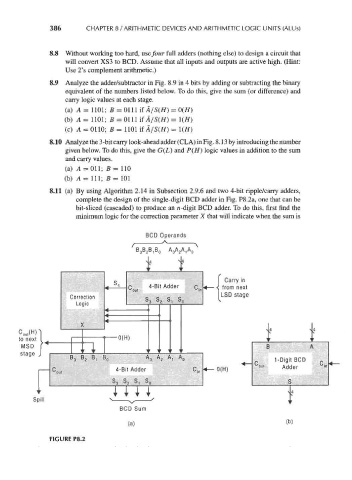
8.11 (a) By using Algorithm 2.14 in Subsection 2.9.6 and two 4-bit ripple/carry adders,
complete the design of the single-digit BCD adder in Fig. P8.2a, one that can be
bit-sliced (cascaded) to produce an n -digit BCD adder. To do this, first find the
minimum logic for the correction parameter X that will indicate when the sum is
BCD Operands
,B 0 A 3 A 2 A,A 0
Carry in
from next
tnp— -N from next
LSD stage
t l- 4*4
L
1-Digit BCD p
001 ir
C mi, 4-Bit Adder 0(H) Adder ° »
'out
S 3 S 2 S t S
Spill
FIGURE P8.2