
Page 666 - Engineering Digital Design
P. 666
13.4 STATE MACHINE DESIGNS 635
\CD 11 \CD \CD 11 \C .
R\ 00 01 10 R\ 00 01 11 10 R\ 00 01 10 B\ 0 1
0 0 0 0 CO 0 s T+V 1 0 0 V 1 0 DV 1
(a) ^ ^ •^
1 0 0 0 1 u T 1 1 1 1 1 1 1 1
^ ^ ^
/ LD / EN / D/U / D/U
\CD \CD \CD
R\ 00 01 11 10 R\ 00 01 11 10 R\ 00 01 11 10
0 fi fi (f) S+T 0 (p r ST 0 (f) (j) (j) 0
^
(b) -€ — 3- -e — 3_ -f — — J_
1 (j) (f) (f) $ 1 (p (f) Y 0 1 r (f) (j) ^ x
\CD
g\. 00 01 11 10
0 0 M if V N if V 0
(c)
1 Q M p
^
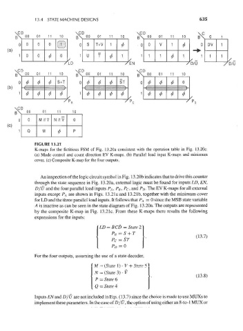
FIGURE 13.21
K-maps for the fictitious FSM of Fig. 13.20a consistent with the operation table in Fig. 13.20c.
(a) Mode control and count direction EV K-maps. (b) Parallel load input K-maps and minimum
cover, (c) Composite K-map for the four outputs.
An inspection of the logic circuit symbol in Fig. 13.20b indicates that to drive this counter
through the state sequence in Fig. 13.20a, external logic must be found for inputs LD, EN,
D/U and the four parallel load inputs P A, P B, P c, and P D. The EV K-maps for all external
inputs except P A are shown in Figs. 13.21a and 13.21b, together with the minimum cover
for LD and the three parallel load inputs. It follows that P A = 0 since the MSB state variable
A is inactive as can be seen in the state diagram of Fig. 13.20a. The outputs are represented
by the composite K-map in Fig. 13.21c. From these K-maps there results the following
expressions for the inputs:
BCD = State 2
PC = ST
P D=Q
For the four outputs, assuming the use of a state decoder,
' M = (State !)• V + State 5
(13.8)
P = State 6
Q = State 4
Inputs £Wand D/U are not included in Eqs. (13.7) since the choice is made to use MUXs to
implement these parameters. In the case of D / U, the option of using either an 8-to-1 MUX or