
Page 662 - Engineering Digital Design
P. 662
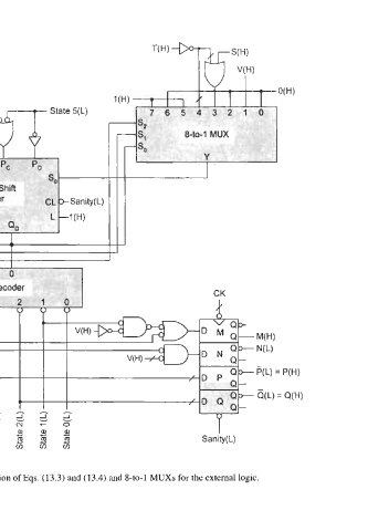
FIGURE 13.17
                         Y
                               8-to-1 MUX

                                    7654321

                                    0


 5

 2
 4

 1
 3
 0
 2
 3-to-8 State Decoder


                                    7
                                    6

                                    5

                                    4
                         Y
                                    3
 D N
 CK
                               8-to-1 MUX
 T
                                    2
 Sanity(L)
 D M  Q
 Q
 1
 ^ Q
                                    1
 Implementation of the FSM in Fig. 13.15a centered around a USR with application of Eqs. (13.3) and (13.4) and 8-to-l MUXs for the external logic.
                                    0
 N(L)
 M(H)
 P(L) = P(H)
 Q(L) = Q(H)