
Page 659 - Engineering Digital Design
P. 659
13.3 STATE MACHINE DESIGNS CENTERED AROUND A SHIFT REGISTER 629
A More Complex Example of State Machine Design Centered around a USR It has
just been demonstrated that a "linear state machine" can be well suited to the use of a
shift register as the memory. However, if this approach is applied to an FSM design where
multiple branchings are involved, use of a USR as the memory element loses some of its
appeal. Consider the state machine in Fig. 13.15a, which is the FSM of Fig. 13.10a but
coded in such a way as to take better advantage of the shift character of the USR. The
branching actions of the USR, defined in Fig. 13.15b, are indicated in parentheses for each
state-to-state transition. As in the previous example, this is very helpful in obtaining the
required logic external to the USR. Notice that the MSB state variable A is left inactive
so as to minimize the external logic commitment — its use is not needed in this case.
Deactivation of a state variable in shift register designs can be done only if care is taken
to ensure that the shifting and parallel load actions do not create problems at this bit
position.
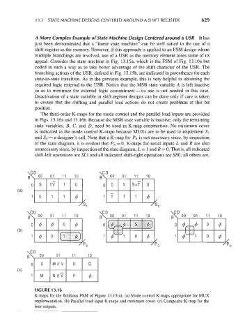
The third-order K-maps for the mode control and the parallel load inputs are provided
in Figs. 13.16a and 13.16b. Because the MSB state variable is inactive, only the remaining
state variables, B, C, and D, need be used in K-map construction. No minimum cover
is indicated in the mode control K-maps because MUXs are to be used to implement S\
and So — a designer's call. Note that a K-map for P A is not necessary since, by inspection
of the state diagram, it is evident that PA = 0. K-maps for serial inputs L and R are also
unnecessary since, by inspection of the state diagram, L = 1 and R = 0. That is, all indicated
shift-left operations are SLl and all indicated shift-right operations are SRO; all others are,
\CD \CD
p\ 00 01 11 10 p\ 00 01 11 10
0 S TV 1 U 0 0 V S+T 0
(a)
1 0 1 1 1 f 1 1
* *
\CD \CD \CD
[X 00 01 11 10 g\ 00 01 11 10 R\ 00 01 11 10
(f) 0 I ^ S ') VY 0 (f)
* ^ Y
(b) 1
#
1
1^0[ (' (j) \ j 1^ <- 1 0 0 ^ /- 0 (f)
0
1 ^
(j)
(f)
^P,
\CD
R\ 00 01 11 10
0 0 M if V 0 Q
(c)
11 M N if V P
*
6
13.1
FIGUR
FIGURE 13.16
E
K-maps for the fictitious FSM of Figure 13.15(a). (a) Mode control K-maps appropriate for MUX
K-maps for
implementation, (b) Parallel load input K-maps and minimum cover, (c) Composite K-map for the
implemental
four outputs