
Page 656 - Engineering Digital Design
P. 656
626 CHAPTER 13 / ALTERNATIVE SYNCHRONOUS FSM ARCHITECTURES
N(L) must be issued from the Q(L) output of the register's flip-flop, or by an inverter on
13.3 STATE MACHINE DESIGNS CENTERED AROUND A SHIFT REGISTER
There are times when the designer might like to consider using an off-the-shelf universal
shift register (USR) in the design of a state machine, one that is amenable to the shifting
character of the USR. Remember, it makes little sense to use a USR for this purpose if
most of the FSM's state-to-state transitions are parallel load actions. For such an FSM, it
would be best to use discrete flip-flops as has been done in all examples up to this point.
In making the state code assignments for an FSM, shifting operations must be given the
highest priority if the most efficient use is to be made of the shift register.
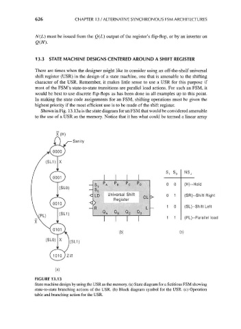
Shown in Fig. 13.13a is the state diagram for an FSM that would be considered amenable
to the use of a USR as the memory. Notice that it has what could be termed a linear array
, S 0 NS,
_
81 PA PB PC PO 0 0 (H)--Hold
— So
-c LD Universal Shift CL > o 1 (SR)--Shift Right
Register
-c
_ 1 (SL)--Shift Left
R L 0
QA QB QC QD
1 1 (PL)--Parallel load
1 1
(b) (c)
FIGURE 13.13
State machine design by using the USR as the memory, (a) State diagram for a fictitious FSM showing
state-to-state branching actions of the USR. (b) Block diagram symbol for the USR. (c) Operation
table and branching action for the USR.