
Page 652 - Engineering Digital Design
P. 652
622 CHAPTER 13 / ALTERNATIVE SYNCHRONOUS FSM ARCHITECTURES
CK
SW 0(H)
S(H) — Debouncing and
synchronizing circuits
Sanity(L)
FIGURE 13.8
Implementation of the one- to three-pulse generator with a six-input, four-output PROM showing the
external logic required to generate pulses conditional on CK.
13.2.4 Design of a More Complex FSM by Using a ROM as the PLD
As a second and more complex example of ROM-centered implementation, consider the
state diagram for a fictitious FSM in Fig. 13.10a. This state machine features four syn-
chronous inputs, one of which is active low, and four outputs, one of which is also active
low. This machine is interesting because it possesses up to three-way branching where
branching is dependent on all four inputs, and has both conditional and unconditional out-
puts. Thus, the ROM program table will be somewhat more complex than that of Fig. 13.6b.
Though this FSM has only seven states, it is as complex (branching-wise) as one is likely
to encounter in the field.
BC
\ 00 01 11 10
CD P = ABC + ABC + ABC
111 101
111 011
(a)
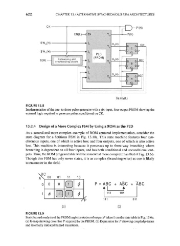
FIGURE 13.9
Static hazard analysis of the PROM implementation of output P taken from the state table in Fig. 13.6a.
(a) K-map showing cover for P required by the PROM, (b) Expression for P showing coupled p-terms
and internally initiated hazard transitions.