
Page 671 - Engineering Digital Design
P. 671
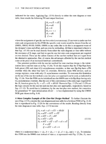
13.5 THE ONE-HOT DESIGN METHOD                                      639


                  indicated for the states. Applying Eqs. (13.9) directly to either the state diagram or state
                  table, there results the following NS and output functions:
                                               D a=aX
                                               D b=aX
                                                                                   (13.10)

                                               D e=dX
                                                Z = e

                 where the assignment of specific one-hot codes is not necessary. If one were to make one-hot
                  state code assignments for this FSM, the specific code words would be chosen from the set
                  (00001, 00010, 00100, 01000, 10000} in any order. But to do this is an apparent waste of
                 the designer's time and effort, and can even be misleading. All that is important to know is
                 that Eqs. (13.10) can be read directly from either the state diagram or state table without
                 the assistance of K-maps, and that no specific one-hot state code assignments are required
                 or even desired. These are the salient features of the one-hot method that set it apart from
                 the alternative approaches. But, of course, the advantages afforded by the one-hot method
                 come at the price of an increased hardware commitment.
                    One potential problem with the one-hot method for state machine design is the initial-
                 ization into a one-hot state as in Fig. 13.24a. To do this requires that the D flip-flops have
                 both preset (PR) and clear (CL) asynchronous overrides, or that one flip-flop have a PR
                 override while the other four have CL overrides. However, many MSI devices, such as
                 storage registers, come with only CL asynchronous overrides. To overcome this limitation
                 on the use of the one-hot method, a one-hot-plus-zero approach can be used, as indicated in
                 Fig. 13.24c. Now the FSM can be initialized into the 00000 state with flip-flops having only
                 CL asynchronous overrides. But the cost of this convenience is the extra logic required for
                 the D a function given by D a = aX + dX + abcde. Shown in Figs. 13.25a and 13.25b are
                 the logic circuits for the one-hot and one-hot-plus-zero approaches, respectively, based on
                 Eqs. (13.10). To avoid fan-in limitations by the one-hot-plus-zero method, the correction
                 for generalized "0" state initialization abcde • • • is best implemented by using the CMOS
                 NOR gate shown in Fig. 8.46.

                 A More Complex Example of the One-Hot Design Method To further illustrate the
                 use of Eqs. (13.9), consider the state diagram and state table for a fictitious FSM in Fig. 11.42
                 that is reproduced in Fig. 13.26 for the convenience of the reader. Reading directly from
                 the state diagram or state table, Eqs. (13.9) become

                                       D a = aS + aT+ eST + abcde
                                       D b = aSf + bSf + cSf
                                       D c = bST + cT + dST
                                                                                   (13.11)
                                       D e=bSf + cSf + df
                                            P =eSf
                                            Q = dST

                 where it is understood that a = Q a, b = Q b, c = Q t, d — Q d, and e = Q e. To initialize
                 this FSM into the 00000 state instead of state a, in agreement with Fig. 13.26a, D a must