
Page 673 - Engineering Digital Design
P. 673
13.5 THE ONE-HOT DESIGN METHOD 641
S+T
\ST '
Qj\ 00 01 11 10
ST
ST
X ' \^S \^_S
S+T
(b)
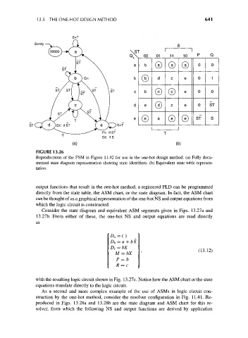
FIGURE 13.26
Reproductions of the FSM in Figure 11.42 for use in the one-hot design method, (a) Fully docu-
mented state diagram representation showing state identifiers, (b) Equivalent state table represen-
tation.
output functions that result in the one-hot method, a registered PLD can be programmed
directly from the state table, the ASM chart, or the state diagram. In fact, the ASM chart
can be thought of as a graphical representation of the one-hot NS and output equations from
which the logic circuit is constructed.
Consider the state diagram and equivalent ASM segments given in Figs. 13.27a and
13.27b. From either of these, the one-hot NS and output equations are read directly
as
D a=()
D b=a
= bx • (m2)
P =b
R = c
with the resulting logic circuit shown in Fig. 13.27c. Notice how the ASM chart or the state
equations translate directly to the logic circuit.
As a second and more complex example of the use of ASMs in logic circuit con-
struction by the one-hot method, consider the resolver configuration in Fig. 11.41. Re-
produced in Figs. 13.28a and 13.28b are the state diagram and ASM chart for this re-
solver, from which the following NS and output functions are derived by application