
Page 674 - Engineering Digital Design
P. 674
642 CHAPTER 13 / ALTERNATIVE SYNCHRONOUS FSM ARCHITECTURES
RiT
R(H)
(a)
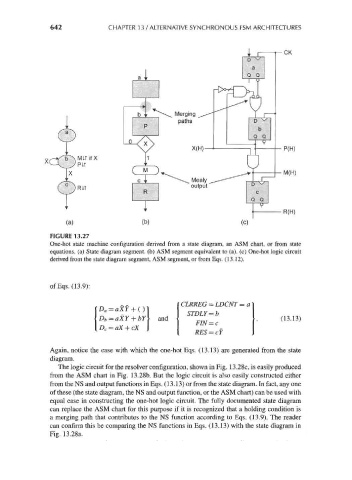
FIGURE 13.27
One-hot state machine configuration derived from a state diagram, an ASM chart, or from state
equations, (a) State diagram segment, (b) ASM segment equivalent to (a), (c) One-hot logic circuit
derived from the state diagram segment, ASM segment, or from Eqs. (13.12).
ofEqs. (13.9):
CLRREG = LDCNT = a
and • (13.13)
*><=<*+<* ' RES=cY
Again, notice the ease with which the one-hot Eqs. (13.13) are generated from the state
diagram.
The logic circuit for the resolver configuration, shown in Fig. 13.28c, is easily produced
from the ASM chart in Fig. 13.28b. But the logic circuit is also easily constructed either
from the NS and output functions in Eqs. (13.13) or from the state diagram. In fact, any one
of these (the state diagram, the NS and output function, or the ASM chart) can be used with
equal ease in constructing the one-hot logic circuit. The fully documented state diagram
can replace the ASM chart for this purpose if it is recognized that a holding condition is
a merging path that contributes to the NS function according to Eqs. (13.9). The reader
can confirm this be comparing the NS functions in Eqs. (13.13) with the state diagram in
Fig. 13.28a.