
Page 678 - Engineering Digital Design
P. 678
646 CHAPTER 13 / ALTERNATIVE SYNCHRONOUS FSM ARCHITECTURES
-Sanity
^<
Start ( _
LDCNTiT
CLREGiT
Start
PSCRY1T if Add/Sub
CLCRYiT if Add/Sub
S,1T
Start
^ ^ ^.CMPLAT if Add/Sub
CNTiT
FINiT if (CNT = 8)
(CNT = 8)
(b) a b C Start CNT=8 Add/Sub
<e 7 * 7 \ 7 ^ 7 ^ 7 •< 7
\x vj V<
M M M
T^TTrt ••- i) s > r — • _|
hpCfart •s f \ f 'S < - • ,
C(CNT=8) - S \ X
'^
aStart -) —1 ^ — v^
bStart - \s — J y — ^
} \
bStart — — J — )e— — r
c(CNT=8) - — J — 3 —^
b(Add/Sub) - — 3 —5 — r
b(Add/Sub) - —3 —? ^ O-H
-^r
c(Add/Sub) — — 5 — ) X
D D h D,, PSCRY CLCRY CMPL FIN
a D C
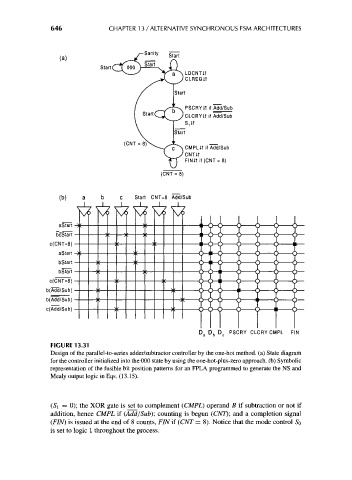
FIGURE 13.31
Design of the parallel-to-series adder/subtractor controller by the one-hot method, (a) State diagram
for the controller initialized into the 000 state by using the one-hot-plus-zero approach, (b) Symbolic
representation of the fusible bit position patterns for an FPLA programmed to generate the NS and
Mealy output logic in Eqs. (13.15).
1
(S , = 0); the XOR gate is set to complement (CMPL) operand B if subtraction or not if
addition, hence CMPL if (Add/Sub)', counting is begun (CNT); and a completion signal
(FIN) is issued at the end of 8 counts, FIN if (CNT = 8). Notice that the mode control 5 0
is set to logic 1 throughout the process.