
Page 682 - Engineering Digital Design
P. 682
650 CHAPTER 13 / ALTERNATIVE SYNCHRONOUS FSM ARCHITECTURES
CK
i i
Sanity Sanity
1
External Control
Inputs Controller Signals Data Path
State Machine Devices
1
Feedback Signals-
Outputs Outputs
Data out
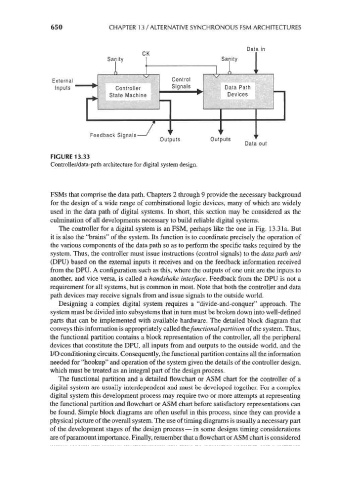
FIGURE 13.33
Controller/data-path architecture for digital system design.
FSMs that comprise the data path. Chapters 2 through 9 provide the necessary background
for the design of a wide range of combinational logic devices, many of which are widely
used in the data path of digital systems. In short, this section may be considered as the
culmination of all developments necessary to build reliable digital systems.
The controller for a digital system is an FSM, perhaps like the one in Fig. 13.3la. But
it is also the "brains" of the system. Its function is to coordinate precisely the operation of
the various components of the data path so as to perform the specific tasks required by the
system. Thus, the controller must issue instructions (control signals) to the data path unit
(DPU) based on the external inputs it receives and on the feedback information received
from the DPU. A configuration such as this, where the outputs of one unit are the inputs to
another, and vice versa, is called a handshake interface. Feedback from the DPU is not a
requirement for all systems, but is common in most. Note that both the controller and data
path devices may receive signals from and issue signals to the outside world.
Designing a complex digital system requires a "divide-and-conquer" approach. The
system must be divided into subsystems that in turn must be broken down into well-defined
parts that can be implemented with available hardware. The detailed block diagram that
conveys this information is appropriately called the functional partition of the system. Thus,
the functional partition contains a block representation of the controller, all the peripheral
devices that constitute the DPU, all inputs from and outputs to the outside world, and the
I/O conditioning circuits. Consequently, the functional partition contains all the information
needed for "hookup" and operation of the system given the details of the controller design,
which must be treated as an integral part of the design process.
The functional partition and a detailed flowchart or ASM chart for the controller of a
digital system are usually interdependent and must be developed together. For a complex
digital system this development process may require two or more attempts at representing
the functional partition and flowchart or ASM chart before satisfactory representations can
be found. Simple block diagrams are often useful in this process, since they can provide a
physical picture of the overall system. The use of timing diagrams is usually a necessary part
of the development stages of the design process — in some designs timing considerations
are of paramount importance. Finally, remember that a flowchart or ASM chart is considered