
Page 680 - Engineering Digital Design
P. 680
648 CHAPTER 13 / ALTERNATIVE SYNCHRONOUS FSM ARCHITECTURES
Add/Sub(H) Y
Y,
(CNT = 8)(H)
Y,
Start(H) Debounce Circuit
Minimum CK
6 X 10X 7
FPLA Y D C(H) D c CNT(H)
D-
D b (H)
Y D
D a(H)
Y LDCNT(L)
CLREG(L)
0(H) — D
CL Q 0-
Sanity(L)
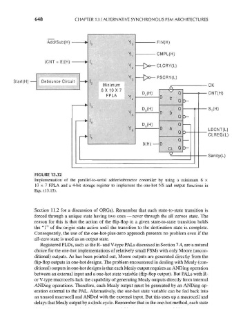
FIGURE 13.32
Implementation of the parallel-to-serial adder/subtractor controller by using a minimum 6 x
10 x 7 FPLA and a 4-bit storage register to implement the one-hot NS and output functions in
Eqs. (13.15).
Section 11.2 for a discussion of ORGs). Remember that each state-to-state transition is
forced through a unique state having two ones — never through the all zeroes state. The
reason for this is that the action of the flip-flop in a given state-to-state transition holds
the "1" of the origin state active until the transition to the destination state is complete.
Consequently, the use of the one-hot-plus-zero approach presents no problem even if the
all-zero state is used as an output state.
Registered PLDs, such as the R- and V-type PALs discussed in Section 7.4, are a natural
choice for the one-hot implementations of relatively small FSMs with only Moore (uncon-
ditional) outputs. As has been pointed out, Moore outputs are generated directly from the
flip-flop outputs in one-hot designs. The problem encountered in dealing with Mealy (con-
ditional) outputs in one-hot designs is that each Mealy output requires an ANDing operation
between an external input and a one-hot state variable (flip-flop output). But PALs with R-
or V-type macrocells lack the capability of generating Mealy outputs directly from internal
ANDing operations. Therefore, each Mealy output must be generated by an ANDing op-
eration external to the PAL. Alternatively, the one-hot state variable can be fed back into
an unused macrocell and ANDed with the external input. But this uses up a macrocell and
delays that Mealy output by a clock cycle. Remember that in the one-hot method, each state