
Page 675 - Engineering Digital Design
P. 675
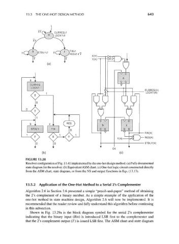
13.5 THE ONE-HOT DESIGN METHOD                                      643


                                  CLRREGiT
                              a
                                } LDCNTiT


                                                       X(H,
                                                       Y(H)


                                                                                    CLRREG(H)
                                                                                     LDCNT(H)


                                                                                    FIN(H)
                                                                                "")—RES(H)
                                                                                    STDLY(H)


                           (b)
                  FIGURE 13.28
                  Resolver configuration of Fig. 11.41 implemented by the one-hot design method, (a) Fully documented
                  state diagram for the resolver. (b) Equivalent ASM chart, (c) One-hot logic circuit constructed directly
                  from the ASM chart, state diagram, or from the NS and output functions in Eqs. (13.13).


                  13.5.2 Application of the One-Hot Method to a Serial 2's Complementer
                  Algorithm 2.6 in Section 2.6 presented a simple "pencil-and-paper" method of obtaining
                  the 2's complement of a binary number. As a simple example of the application of the
                  one-hot method in state machine design, Algorithm 2.6 will now be implemented. It is
                  recommended that the reader review and fully understand this algorithm before continuing
                  in this subsection.
                    Shown in Fig. 13.29a is the block diagram symbol for the serial 2's complementer
                  indicating that the binary input (Bin) is introduced LSB first to the complementer and
                  that the 2's complement output (T) is issued LSB first. The ASM chart and state diagram