
Page 676 - Engineering Digital Design
P. 676
644 CHAPTER 13 / ALTERNATIVE SYNCHRONOUS FSM ARCHITECTURES
Two's
Binary in
LSB First — * Serial Two's Complement Start(L)
~* LSB out First
(Bin) Complementer | " ff)"""
(T)
(a)
Bin(H)
T b i r
C -•0 Complement •0
remainder
L i L
Sanity(L)
0 X>jn\ 1 TIT if (aBin + bBin)
(b) (c) (d)
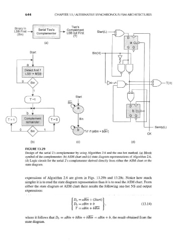
FIGURE 13.29
Design of the serial 2's complementer by using Algorithm 2.6 and the one-hot method, (a) Block
symbol of the complementer, (b) ASM chart and (c) state diagram representations of Algorithm 2.6.
(d) Logic circuit for the serial 2's complementer derived directly from either the ASM chart or the
state diagram.
expressions of Algorithm 2.6 are given in Figs. 13.29b and 13.29c. Notice how much
simpler it is to read the state diagram representation than it is to read the ASM chart. From
either the state diagram or ASM chart there results the following one-hot NS and output
expressions:
D a = aBin
D b = aBin + b (13.14)
T = aBin + bBin
where it follows that Db = aBin + bBin + bBin = aBin + b, the result obtained from the
state diagram.