
Page 668 - Engineering Digital Design
P. 668
-.
2
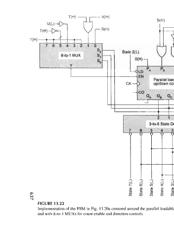
FIGURE 13.22
T(H)
1
1
1 |
V(H)
c
o
c
and with 8-to-l MUXs for count enable and direction controls.
o
c
5
o
2
c
4
S(H)
rorororororororo o
1
c
3
o
0
T(H)
c
2
3-to-8 State Decoder
o
w
c
o
»-
»
CK
Sanity(L)
s
2
1
N(L)
M(H)
Implementation of the FSM in Fig. 13.20a centered around the parallel loadable up/down counter of Fig. 12.26 with application of Eqs. (13.7) and (13.8)
P(L) = P(H)
Q(L) = Q(H)