
Page 688 - Engineering Digital Design
P. 688
656 CHAPTER 13 / ALTERNATIVE SYNCHRONOUS FSM ARCHITECTURES
J^axim_u_m_sjpeed_ „ \ Linear angular
deceleration
N
i i
.' \ HA I T^ V
O
_g
>
CB
L
o, _,^- ,_ _, ' ' ,_HALT
c
Time
(a)
Sanity(L)
i STEPCK
_i I
STEP pulses required I
SYSCK for linear angular ^/
acceleration
Motor
GO(H)- 4-Bit shaft
Control _jL_JL_jL_n_TLJL
SIPO ^ ' *[ Stepping motor
HOLD(H)- system STEP(H)
register
HALT(H)-
(b)
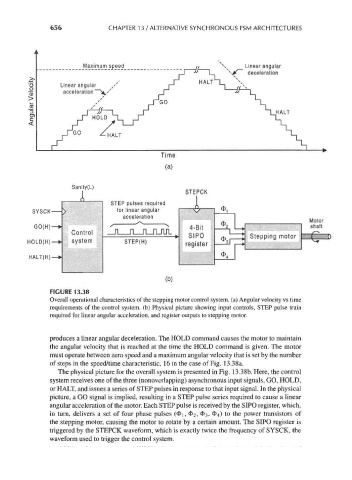
FIGURE 13.38
Overall operational characteristics of the stepping motor control system, (a) Angular velocity vs time
requirements of the control system, (b) Physical picture showing input controls, STEP pulse train
required for linear angular acceleration, and register outputs to stepping motor.
produces a linear angular deceleration. The HOLD command causes the motor to maintain
the angular velocity that is reached at the time the HOLD command is given. The motor
must operate between zero speed and a maximum angular velocity that is set by the number
of steps in the speed/time characteristic, 16 in the case of Fig. 13.38a.
The physical picture for the overall system is presented in Fig. 13.38b. Here, the control
system receives one of the three (nonoverlapping) asynchronous input signals, GO, HOLD,
or HALT, and issues a series of STEP pulses in response to that input signal. In the physical
picture, a GO signal is implied, resulting in a STEP pulse series required to cause a linear
angular acceleration of the motor. Each STEP pulse is received by the SIPO register, which,
in turn, delivers a set of four phase pulses (4>i, 4>2> 03, $4) to the power transistors of
the stepping motor, causing the motor to rotate by a certain amount. The SIPO register is
triggered by the STEPCK waveform, which is exactly twice the frequency of SYSCK, the
waveform used to trigger the control system.