
Page 698 - Engineering Digital Design
P. 698
664 CHAPTER 13 / ALTERNATIVE SYNCHRONOUS FSM ARCHITECTURES
HOLD(H
> - ID - *STDLY(H)
Y 0
INCDLY(H)
•>DECDLY(H)
SYSCK —
J-^STEP(H)
-{>o—»• LDDLY(L)
->LDZERO(H)
9 x 20 x 8
FPLA
'2
Sanity(L)
Sanity(L) i i v
H
D C ( ) Q
CNT(H) C
MXDLY(H) D B(H)
D B
'6
Q
MNDLY(H) I
D A (H)
D A
Q
0(H)H
SYSCK
"7~~\ U W I 1 •
STEPCK-
Divide-by-two
counter
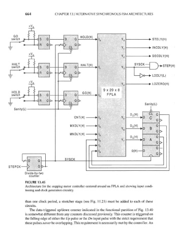
FIGURE 13.45
Architecture for the stepping motor controller centered around an FPLA and showing input condi-
tioning and clock generation circuitry.
than one clock period, a stretcher stage (see Fig. 11.21) must be added to each of these
circuits.
The data-triggered up/down counter indicated in the functional partition of Fig. 13.40
is somewhat different from any counters discussed previously. This counter is triggered on
the falling edge of either the Up pulse or the Dn input pulse with the strict requirement that
these pulses never be overlapping. This requirement is necessarily met by the controller. An