
Page 712 - Engineering Digital Design
P. 712
678 CHAPTER 13 / ALTERNATIVE SYNCHRONOUS FSM ARCHITECTURES
S
\
0000000 }*—Sanity
X©Y
inputs to and outputs from that flip-flop. Do not implement the logic for flip-
flops b and c.
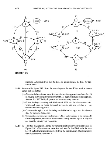
13.16 Presented in Figure PI3.10 are the state diagrams for two FSMs, each with two
inputs and one output.
(1) Given the indicated state identifiers, use the one-hot approach to obtain the NS
and output expressions for each of these FSMs directly from the state diagrams.
Assume that RET D flip-flops are used as the memory elements.
(2) Obtain the logic necessary to initialize each FSM into the all-zero state after
which each must be forced to transit irreversibly into one-hot state a — the
one-hot-plus-zero approach.
(3) Construct the logic circuit, including the initialization logic into the all-zero
state for each one-hot design.
(4) Comment on the presence or absence of ORGs and s-hazards in the outputs. If
ORGs are possible, indicate where they exist and by what race path. If they are
not possible, explain your reasoning.
13.17 (a) The state diagram for a candy bar vending machine controller is presented in
Figure P13.2. Given the state identifiers indicated for this FSM, write the one-
hot NS and output expressions directly from the state diagram. Plan to initialize
directly into the one-hot state a.