
Page 715 - Engineering Digital Design
P. 715
PROBLEMS 681
door opening mechanisms are available to the designer. No acknowledge signal
following an increment is necessary from the counters. Finally, make certain that
all required input conditioning circuits are included.
13.21 A traffic light control system is to be designed that will operate traffic lights at the
intersection of a main highway and an infrequently used farm road. Traffic sensors
are placed on both the highway and the farm road to indicate when traffic is present.
If no traffic is sensed on the farm road, traffic on the highway is allowed to flow. But
when a vehicle activates the sensor on the farm road, the highway light signals are
activated immediately if the traffic sensor on the highway is not active. Otherwise,
the vehicle on the farm road must wait 30 seconds or until the highway is clear,
whichever occurs first, before the highway signals are reactivated. Once the farm
road is clear, the system must activate the farm and highway lights so as to permit
highway traffic to flow, but only after a 30-second time interval to allow the farm
road to clear.
In designing the control system, two interval timers (counters) must be designed,
one for the 30 second time interval and the other for the 5-second yellow light time
interval. These timers accept an input to signal the start of the time interval and
return an output to indicate the end of the time interval. Upon receiving the count
enable input signal, the timer begins timing. At the end of the specified time, the
output signal is activated and remains active until the count enable input signal is
deactivated.
Construct a suitable controller state diagram and functional partition for the
traffic light control system. Make any reasonable state code assignment for the
controller and use an architecture centered around a PLA, as in Figure 13.1. Con-
struct the p-term table for programming the PLA device and provide a block dia-
gram for the controller. Assume that all inputs and outputs are active high. Use the
abbreviations given next and assume that F and H are asynchronous inputs.
Controller Inputs: F = Farm road active; H = Highway active; 30 =30
seconds complete; 5= 5 seconds complete.
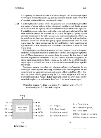
Sanity
A
EL - Enter light on
VI -- Voter in
Voter Booth OL -- Occupied lignt on
Controller DC -- Door closed
DO -- Door open
Ba- Button a pushed
INCRa -- Increment counter a
Bb-- Button b pushed
INCRb -- Increment counter b
(a) (b)
FIGURE P13.12