
Page 711 - Engineering Digital Design
P. 711
PROBLEMS 677
S(H)-i r-T(H) S(H} D(H) H)
.ii, i i V
•S(H)
7 6 5 4 3 2 1 0
B(H)-S 2 LD B(H)-S 2 B(H)-
C(H)- S, MUX C(H)- S, ENMUX C(H)-
P P P P n —
'A'a'f^'
LD A B c D D/U
EN Parallel Loadable , Co n -t, i\ \
S Up/Dn Counter CL^ San,ty(L)
CO Cl
Q 4 Q B Q^ Q n
B(H)
C(H) f
T(H)
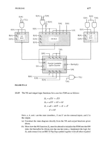
FIGURE P13.9
13.15 The NS and output logic functions for a one-hot FSM are as follows:
D a=aXY + cXY
Z = bY
Here, a, b, and c are the state identifiers, X and Y are the external inputs, and Z is
the output.
(a) Construct the state diagram directly from the NS and output functions given
above.
(b) Show how the NS function D a must be altered to initialize the FSM into the 000
state, but thereafter be driven into the one-hot state a. Implement the logic for
D a and connect it to an RET D flip-flop symbol together with all other required