
Page 706 - Engineering Digital Design
P. 706
672 CHAPTER 13 / ALTERNATIVE SYNCHRONOUS FSM ARCHITECTURES
cm
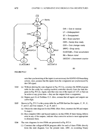
Sanity
CIR = Coin in receiver
LT = Underpayment
GT = Overpayment
EQ = Exact payment
CDR = Candy drop ready
CCR = Coin changer ready
DRPC = Drop candy
CLACCUM = Clear accumulator
RN = Return nickel
DECCNT = Decrement counter
CLACCUMIt DECCNTiT
(a) (b)
FIGURE P13.2
note that synchronizing of the inputs is not necessary for GO/NO-GO branching
actions. Also, assume that the inputs from the comparator are synchronized by
the CIR signal.
13.4 (a) Without altering the state diagram in Fig. P13.2a, construct the ROM program
table for the candy bar vending machine controller directly from the state dia-
gram in Fig. P13.2a. Again, note that only one of the inputs LT, GT, or EQ can
be active at any given time — they are the outputs from a comparator,
(b) Repeat part (b) of Problem 13.3. Also, assume that all inputs and outputs are
active high.
13.5 Shown in Fig. P13.3 is the p-term table for an FSM that has five inputs, U, W, X,
Y, and Z, and four outputs, P, Q, R, and S.
(a) Obtain the state diagram for this FSM. (Hint: First, construct the NS and output
K-maps.)
(b) Run complete ORG and hazard analyses on this FSM. If these timing defects
exist in any of the outputs, indicate what corrective action is most appropriate
to eliminate them.
13.6 The state diagrams for two FSMs are presented in Fig. PI3.4.
(1) Construct the collapsed ROM program table for each of these FSMs directly
from the state diagram. List the present state, ABC, in ascending binary