
Page 724 - Engineering Digital Design
P. 724
690 CHAPTER 14 / ASYNCHRONOUS STATE MACHINE DESIGN AND ANALYSIS
f (x) Unconditional
a
' ' output
Branching
^ paths
PS variables
Branching
_, L - -, , _^ conditions
State code
assignment
Conditional
f c( Xj) output
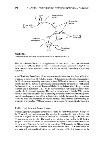
FIGURE 14.4
Fully documented state diagram as interpreted for an asynchronous FSM.
Thus, there is no difference in the applications of these rules to either synchronous or
asynchronous FSMs. See Problem 10.24 for more information on the relationship between
these two rules, and a more direct means of testing for mutually exclusivity of branching
conditions.
ASM Charts and Flowcharts Flowcharts were used in Subsection 11.9.2 and ASM charts
were used in Subsections 11.10.1, 13.5.2, and 13.6.2 as thinking tools in the construction of
the fully documented state diagrams for synchronous FSM design. So also can these thinking
tools be used for the purpose of constructing state diagrams for asynchronous FSM design.
Furthermore, it may be recalled that the ASM chart is used effectively to design a one-hot
state machine in Subsection 13.5.2, but the fully documented state diagram is shown to be
equally effective for such a purpose. The point to be made here is that the ASM chart or
flowchart should be considered only as a thinking tool in the construction of the fully docu-
mented state diagrams or state tables. In this text, it is the fully documented state diagram or
state table that is considered to be the simplest and most effective means of representing the
sequential behavior of an FSM (synchronous or asynchronous) in preparation for its design.
14.5.2 Next-State and Output K-maps
When using the LPD model for asynchronous FSMs, the entered variable (EV) K-maps for
the NS variables are easily constructed by applying the mapping algorithm in Section 10.6
to the state diagram and the excitation table for the LPD model in Fig. 14.3b. Thus, this
NS mapping process for the LPD model is very similar to that used in the D flip-flop
designs of synchronous FSMs, the only difference being the nomenclature for the PS and
NS parameters. Shown in Fig. 14.5 are the generalized EV K-maps for the NS and output
functions as applied to the LPD model of an asynchronous FSM. The K-maps are of the
mth order with state variables for their axes and inputs as the EVs. It is important for the