
Page 726 - Engineering Digital Design
P. 726
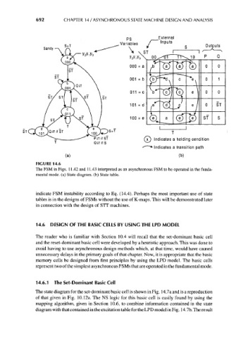
692        CHAPTER 14 / ASYNCHRONOUS STATE MACHINE DESIGN AND ANALYSIS


                                                                       External
                                                                       Inputs
                        Sanity


                                                                            T
                                                                 (IT) Indicates a holding condition
                                                                v /
                                            CUT if S             -
                                                                ^ * Indicates a transition path
                                 (a)                                           (b)
                     FIGURE 14.6
                     The FSM in Figs. 11.42 and 11.43 interpreted as an asynchronous FSM to be operated in the funda-
                     mental mode, (a) State diagram, (b) State table.


                     indicate FSM instability according to Eq. (14.4). Perhaps the most important use of state
                     tables is in the designs of FSMs without the use of K-maps. This will be demonstrated later
                     in connection with the design of STT machines.


                     14.6 DESIGN OF THE BASIC CELLS BY USING THE LPD MODEL

                     The reader who is familiar with Section 10.4 will recall that the set-dominant basic cell
                     and the reset-dominant basic cell were developed by a heuristic approach. This was done to
                     avoid having to use asynchronous design methods which, at that time, would have caused
                     unnecessary delays in the primary goals of that chapter. Now, it is appropriate that the basic
                     memory cells be designed from first principles by using the LPD model. The basic cells
                     represent two of the simplest asynchronous FSMs that are operated in the fundamental mode.


                     14.6.1 The Set-Dominant Basic Cell
                     The state diagram for the set-dominant basic cell is shown in Fig. 14.7a and is a reproduction
                     of that given in Fig. 10.12a. The NS logic for this basic cell is easily found by using the
                     mapping algorithm, given in Section 10.6, to combine information contained in the state
                     diagram with that contained in the excitation table for the LPD model in Fig. 14.7b. The result