
Page 730 - Engineering Digital Design
P. 730
696 CHAPTER 14/ASYNCHRONOUS STATE MACHINE DESIGN AND ANALYSIS
Q S R
A A 0 $A t +A 0 )
rt
l*0
P8o: J
1 0
$A 1+A 0) 1 A t A 0
PS 1 J 1 0 1 V . ) / v , y
/S /
S "" A A R — A A
II
~~ F\ A r\ «
~~ r\ j f\ j-.
(b) (c)
y'"/
-Y(L)
r ' i—'
(e)
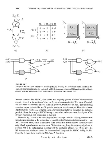
FIGURE 14.11
Design of the two-input rendezvous module (RMOD) by using the nested cell model, (a) State dia-
gram, (b) Excitation table for the basic cell, (c) NS K-maps and minimum NS functions, (d), (e) Logic
circuits with and without the fictitious LPD memory element for the basic cell.
become inactive. The RMOD, also known as a majority gate or Muller C (concurrency)
module, is used in the design of other useful asynchronous circuits. The name C-module
has also been used for this device. In effect, the RMOD acts like an AND gate in issuing
an active output but acts like an OR gate in issuing an inactive output. Thus, the external
inputs must all rendezvous with the same activation level before a change in the output is
possible. Since the acronym RMOD is easy to remember and seems more descriptive of the
device's function, it will be retained in this text.
Shown in Fig. 14.1 la is the state diagram for a two-input RMOD. Clearly, the transition
from the inactive state to the active state is possible only if both inputs become active — an
AND function. Then, while in the active state, a transition to the inactive state is possible
only if both inputs become inactive — an OR function. Applying the mapping algorithm in
Section 10.6 to the state diagram together with the excitation table of Fig. 10.15c gives the
NS K-maps and minimum covers for the nested cell design of the RMOD in Fig. 14.1 Ic.
From the K-maps there results the NS S and R functions
(14.7)
S = AiA Q and R = AiA 0