
Page 404 - Subyek Computer Aided Design - [David Planchard] Engineering Design with SOLIDWORKS
P. 404
Extrude and Revolve Features Engineering Design with SOLIDWORKS® 2018
BA TTERYPLATE Part • Extruded Boss Feature
The Holder is created with a circular Extruded
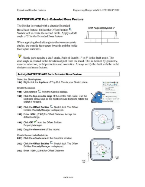
Boss/Base feature. Utilize the Offset Entities ~ Draft Angle displayed at 5°
Sketch tool to create the second circle. Apply a draft
angle of 3 ° in the Extruded Boss feature.
When applying the draft angle to the two concentric
circles, the outside face tapers inwards and the inside
face tapers outwards.
, 1 /
-;Q;. Plastic parts require a draft angle. Rule of thumb: 1 ° to 5° is the draft angle. The
draft angle is created in the direction of pull from the mold. This is defined by geometry,
material selection, mold production and cosmetics. Always verify the draft with the mold
designer and manufacturer.
I Activity BATTERYPLATE Part - Extruded Boss Feature
Select the Sketch plane.
194) Right-click the top face of Top Cut. This is your Sketch plane. fi ~ ~ ! e, +, ~· ~
~~ ~~ fi> ~ ®ll
Create the sketch. @k~tchJn Tools
Zoom/Pan/ Rotate
195) Click Sketch L from the Context toolbar. Recent Commands
Face
196) Click the top circular edge of the center hole. Note: Use the ,.j Change Transparency
keyboard arrow keys or the middle mouse button to rotate the 01 Create Plane Parallel to Sc
sketch if needed. Feature (Top Cut )
197) Click the Offset Entities ~ Sketch tool. The Offset
Entities PropertyManager is displayed.
0
198) Enter .300in, [7.62] for Offset Distance. Accept the
default settings.
199) Click OK ~ from the Offset Entities
PropertyManager.
,- [7.62]
.300
200) Drag the dimension off the model.
Create the second offset circle.
201) Click the offset circle in the Graphics window.
202) Click the Offset Entities ~ Sketch tool. The Offset
Entities PropertyManager is displayed.
...
203) Enter .1 OOin, [2.54] for Offset Distance.
1- [7.62]
.300
[2.54] ~
.100
PAGE 5 - 36