
Page 407 - Subyek Computer Aided Design - [David Planchard] Engineering Design with SOLIDWORKS
P. 407
Engineering Design with SOLIDWORKS® 2018 Extrude and Revolve Features
Display an Isometric view with Hidden Lines Removed. Save the ~ ~ Top Cut
BATTERYPLA TE.
IB TopFillet
228) Click Isometric view ~ .
~ ~ Holes
229) Click Hidden Lines Removed © from the Heads-up View toolbar. ~ ~ Holder
4- ,. \..
I
230) Drag the Rollback bar to the bottom of
the FeatureManager.
231) Click Save ~ - Radius: O.OSin
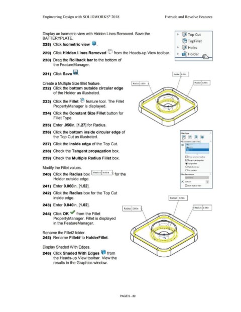
Create a Multiple Size fillet feature. Radius: O.OSin Radius: 0.05in
232) Click the bottom outside circular edge
of the Holder as illustrated.
233) Click the Fillet ® feature tool. The Fillet
PropertyManager is displayed.
234) Click the Constant Size Fillet button for
Fillet Type.
235) Enter .050in, [1.27] for Radius.
236) Click the bottom inside circular edge of Fillet Type A
[i]
the Top Cut as illustrated. ~ ~ ~
2
It ro Constant Size Fillet
237) Click the inside edge of the Top Cut. © Edge<l >
Edge<2>
238) Check the Tangent propagation box. jEdge<3>
~
239) Check the Multiple Radius Fillet box. jv j Show selection toolbar
G2) Tangent propagation
@ Full preview
Modify the Fillet values. O Partial preview
0No preview
240) Click the Radius box I Rad ius: I O.OSin R for the Fillet Parameters
Holder outside edge. Sym1netric --
f:_, 0.0SOin £
241) Enter 0.060in, [1.52]. 0 Multi Radius Fillet
242) Click the Radius box for the Top Cut
inside edge. Radius: O.OSin
243) Enter 0.040in, [1.02].
Radius: o.06in Radius: 0.04in
244) Click OK ~ from the Fillet
PropertyManager. Fillet is displayed
in the FeatureManager. I ,, ......
.. --· .. ,
r .... ___ __ ,..,:
Rename the Fillet2 folder.
245) Rename Fillet# to HolderFillet.
Display Shaded With Edges.
246) Click Shaded With Edges e from
the Heads-up View toolbar. View the
results in the Graphics window.
PAGE5-39