
Page 412 - Subyek Computer Aided Design - [David Planchard] Engineering Design with SOLIDWORKS
P. 412
Extrude and Revolve Features Engineering Design with SOLIDWORKS® 2018
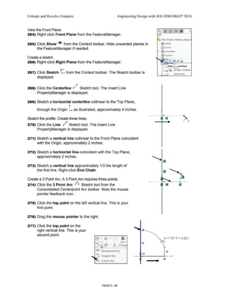
View the Front Plane.
264) Right click Front Plane from the FeatureManager.
LENS (Default< <Default> _Display S
265) Click Show from the Context toolbar. Hide unwanted planes in [€) J History
the FeatureManager if needed. iftJ Sensors
~ IA] Annotations
[fJ Equations
Create a sketch.
fo>~
266) Right-click Right Plane from the FeatureManager. : Fro?ina\~ ~ ::::::::::====I
Q To Feat\ Show l"t Plane)
Q Rig IQ 0 3.0 Sketch On Plane
267) Click Sketch L. from the Context toolbar. The Sketch toolbar is
Ori Section View
displayed.
~p
268) Click the Centerline d ~ Sketch tool. The Insert Line
PropertyManager is displayed.
269) Sketch a horizontal centerline collinear to the Top Plane,
through the Origin _L as illustrated, approximately 4 inches.
Sketch the profile. Create three lines.
270) Click the Line / Sketch tool. The Insert Line
PropertyManager is displayed.
271) Sketch a vertical line collinear to the Front Plane coincident
with the Origin, approximately 2 inches.
272) Sketch a horizontal line coincident with the Top Plane,
approximately 2 inches.
273) Sketch a vertical line approximately 1 /3 the length of
the first line. Right-click End Chain.
Create a 3 Point Arc. A 3 Point Arc requires three points.
274) Click the 3 Point Arc {°) Sketch tool from the
Consolidated Centerpoint Arc toolbar. Note the mouse
pointer feedback icon.
275) Click the top point on the left vertical line. This is your
first point.
276) Drag the mouse pointer to the right.
277) Click the top point on the
right vertical line. This is your
second point.
0 · N · :1 _ A = 72° R = 0 .821
Trim I
-:> · @ · A Entitie
~ Centerpoint Arc I
-- ,. ____ ____.__ -.
-:) Tangent Arc
..
3 Point Arc
PAGE 5-44