
Page 415 - Subyek Computer Aided Design - [David Planchard] Engineering Design with SOLIDWORKS
P. 415
Engineering Design with SOLIDWORKS® 2018 Extrude and Revolve Features
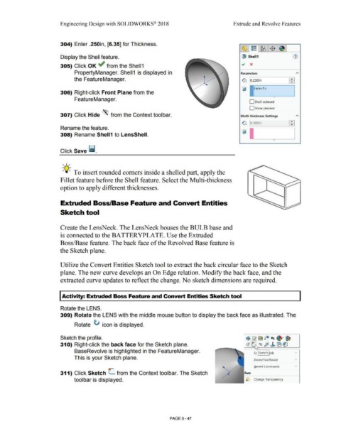
304) Enter .250in, [6.35] for Thickness.
-(§ ·1 (rn I ~ ·1 $ J
Display the Shell feature. l!) Shell1
.., x
305) Click OK ~ from the Shell 1
PropertyManager. Shell 1 is displayed in Parameters
the FeatureManager. ~ lo.2soin EEi
r------,
~ Face<1>
306) Right-click Front Plane from the
•
FeatureManager.
D Shell outward
D Show preview
307) Click Hide '\ from the Context toolbar. Multi-thickness Settings
~ § ooin
Rename the feature.
308) Rename Shell1 to LensShell.
•
Click Save ii.
, 1,,
-;Q~ To insert rounded comers inside a shelled part, apply the
Fillet feature before the Shell feature. Select the Multi-thickness
option to apply different thicknesses.
Extruded Boss/Base Feature and Convert Entities
Sketch tool
Create the LensNeck. The LensNeck houses the BULB base and
is connected to the BATTERYPLATE. Use the Extruded
Boss/Base feature. The back face of the Revolved Base feature is
the Sketch plane.
Utilize the Convert Entities Sketch tool to extract the back circular face to the Sketch
plane. The new curve develops an On Edge relation. Modify the back face, and the
extracted curve updates to reflect the change. No sketch dimensions are required.
I Activity: Extruded Boss Feature and Convert Entities Sketch tool
Rotate the LENS.
309) Rotate the LENS with the middle mouse button to display the back face as illustrated. The
Rotate ti icon is displayed.
Sketch the profile. ~ ~~ !e +i ~· ~
31 O) Right-click the back face for the Sketch plane. ~ ® p ,J. (B~
BaseRevolve is highlighted in the FeatureManager. S Sketch ols •
This is your Sketch plane.
Zoom/Pan/Rotate •
Recent Commands •
311) Click Sketch L from the Context tool bar. The Sketch Face
toolbar is displayed. Change Transparency
PAGE5-47