
Page 414 - Subyek Computer Aided Design - [David Planchard] Engineering Design with SOLIDWORKS
P. 414
Extrude and Revolve Features Engineering Design with SOLIDWORKS® 2018
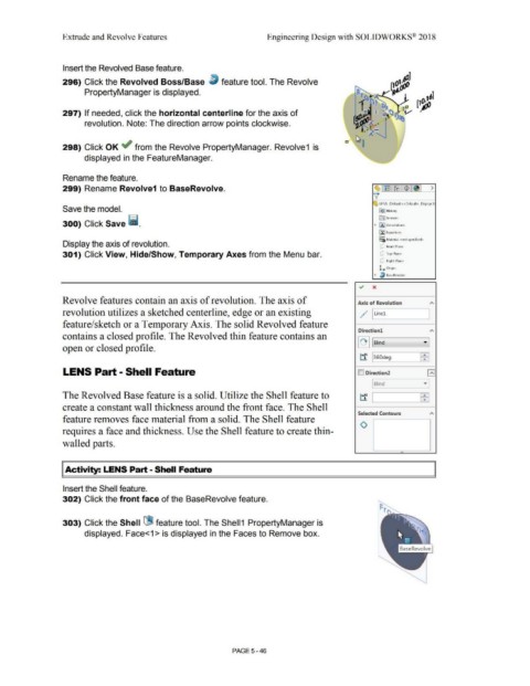
Insert the Revolved Base feature.
296) Click the Revolved Boss/Base ~ feature tool. The Revolve
PropertyManager is displayed.
297) If needed, click the horizontal centerline for the axis of
revolution. Note: The direction arrow points clockwise.
298) Click OK ~ from the Revolve PropertyManager. Revolve1 is
displayed in the FeatureManager.
Rename the feature.
299) Rename Revolve1 to BaseRevolve.
' LENS (Defautt<<Defoult> Displ~y S
Save the model. (E)] Hi~tory
300) Click Save ii. • IA} l\nnotations
trnse,,w rs
ll:J Fqu11tion~
o-
::::c; Material <not specified>
Display the axis of revolution. CJ Front Pl~ne
301) Click View, Hide/Show, Temporary Axes from the Menu bar. (J Top Plane
(J Right Plane
L Origin
• l) B<1seRevolvP
<./ x
Revolve features contain an axis of revolution. The axis of
Axis of Revolution
"
revolution utilizes a sketched centerline, edge or an existing . ;· I Linel
•
• I
feature/sketch or a Temporary Axis. The solid Revolved feature
Direction! "
contains a closed profile. The Revolved thin feature contains an
I '+ 11 Blind · ]
open or closed profile.
tf 1360deg ffil
LENS Part - Shell Feature ID Direction2 r~
-·
"·
[ Blind •
'
The Revolved Base feature is a solid. Utilize the Shell feature to tf I ffil
create a constant wall thickness around the front face. The Shell
Selected Contours "
feature removes face material from a solid. The Shell feature
0
requires a face and thickness. Use the Shell feature to create thin-
walled parts.
"'
I Activity: LENS Part - Shell Feature
Insert the Shell feature.
302) Click the front face of the BaseRevolve feature.
303) Click the Shell (jBJ feature tool. The Shell1 PropertyManager is
displayed. Face<1 > is displayed in the Faces to Remove box.
PAGE 5 - 46