
Page 413 - Subyek Computer Aided Design - [David Planchard] Engineering Design with SOLIDWORKS
P. 413
Engineering Design with SOLIDWORKS® 2018 Extrude and Revolve Features
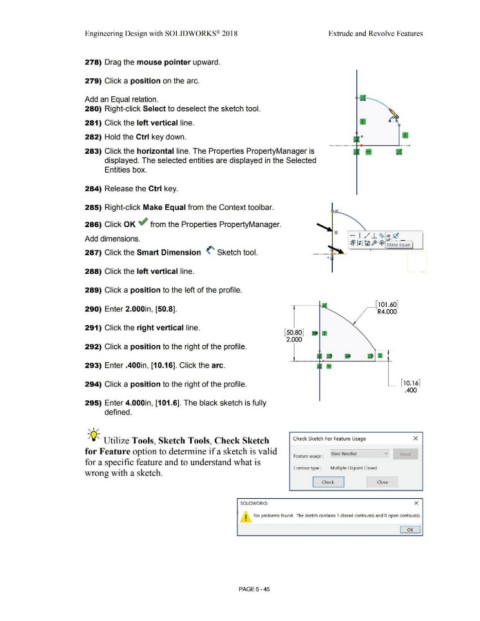
278) Drag the mouse pointer upward.
279) Click a position on the arc.
Add an Equal relation.
280) Right-click Select to deselect the sketch tool.
281) Click the left vertical line.
282) Hold the Ctrl key down.
283) Click the horizontal line. The Properties PropertyManager is
displayed. The selected entities are displayed in the Selected
Entities box.
284) Release the Ctrl key.
285) Right-click Make Equal from the Context toolbar.
286) Click OK ~ from the Properties PropertyManager.
- I ,,·" ..l.. ~ - 'c
Add dimensions. )It:'._ _ _
rB1 1: 1 tfl ft> ~ Make Equal
287) Click the Smart Dimension <'- Sketch tool.
288) Click the left vertical line.
289) Click a position to the left of the profile.
~[101.60]
290) Enter 2.000in, [50.8]. R4.000
291) Click the right vertical line.
[50.80]
2.000
292) Click a position to the right of the profile.
293) Enter .400in, [10.16]. Click the arc.
294) Click a position to the right of the profile. [ 10.16]
.400
295) Enter 4.000in, [101.6]. The black sketch is fully
defined.
, ,.,.
-;Q~ Utilize Tools, Sketch Tools, Check Sketch Check Sketch For Feature Usage x
for Feature option to determine if a sketch is valid
Feature usage : I Base Revolve Reset
for a specific feature and to understand what is
Contour type : Multiple Disjoint Closed
wrong with a sketch.
L Close ~
Check
SOLIDWORKS x
I No problems found. The sketch contains 1 closed contour(s) and O open contour(s) .
•
OK
PAGE5 - 45