
Page 419 - Subyek Computer Aided Design - [David Planchard] Engineering Design with SOLIDWORKS
P. 419
Engineering Design with SOLIDWORKS® 2018 Extrude and Revolve Features
• Sketch profile ( Center point arc)
• Axis of Revolution (Temporary axis)
• Angle of Rotation (360)
• Thickness .lOOin [2.54]
A Revolved feature produces silhouette edges in 20 views. A silhouette edge represents
the extent of a cylindrical or curved face.
Select the Temporary Axis for Axis of Revolution. Select the Revolved Boss feature.
Enter. lOOin [2.54] for Thickness in the Revolve PropertyManager. Enter 360° for Angle
of Revolution.
I Activity: LENS Part - Revolved Boss Thin Feature
Create a sketch.
353) Right-click Right Plane from the FeatureManager.
354) Click Sketch (_ from the Context toolbar.
Irim Convert
(9 • /A. Entities Entities
355) Click Right view @.
Centerpoint Arc
") Tangent Arc
356) Zoom in on the LensNeck.
~ 3 Point Arc
9
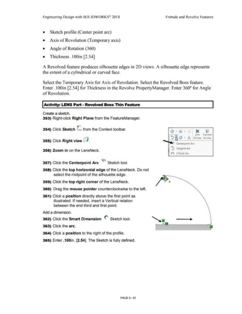
357) Click the Centerpoint Arc Sketch tool.
358) Click the top horizontal edge of the LensNeck. Do not
select the midpoint of the silhouette edge.
359) Click the top right corner of the LensNeck.
360) Drag the mouse pointer counterclockwise to the left.
361) Click a position directly above the first point as
illustrated. If needed, insert a Vertical relation
between the end third and first point.
Add a dimension.
362) Click the Smart Dimension <' Sketch tool.
363) Click the arc.
364) Click a position to the right of the profile.
365) Enter .100in, [2.54]. The Sketch is fully defined.
PAGE5-51