
Page 422 - Subyek Computer Aided Design - [David Planchard] Engineering Design with SOLIDWORKS
P. 422
Extrude and Revolve Features Engineering Design with SOLIDWORKS® 2018
.
Verify the position of the extruded feature. I
389) Click the Top view @ . View the extruded feature.
I
I
Rename the feature. Display an Isometric view. Save the model. I
I
390) Rename Boss-Extrude2 to LensCover. I
I
I
391) Click Isometric view ~ .
I
392) Click Save ii.
~ color
LENS Part - Extruded Boss Feature and Transparency
I Basic ~dvance~
Apply the Extruded Boss/Base feature to create the LensShield. iii Color/Image <>.. Mapping
~ Illumination U Surface Finish
Utilize the Convert Entities Sketch tool to extract the inside circular Illumination " "
edge of the LensCover and place it on the Front plane. O Dynamic help
Oiffuse amount:
•
1.00
•
T '
Apply the Transparent Optical property to the LensShield to control Specular amount:
•
0.50 •
the ability for light to pass through the surface. Transparency is an 1 ; l
Specular color:
Optical Property found in the Color PropertyManager. Control the
following properties: Specular spread/Blurriness:
0.6875 •
•
Reflection amount (RealView only):
• Diffuse amount, Specular amount, Specular spread,
•
0.233 •
Reflection amount, Transparent amount and Luminous l 1 1
O Blurry reflections
intensity. Transparent amount:
•
0.00
• __.
Luminous intensity:
•
o.oo w/srm" 2 >-;;
I Activity: LENS Part - Extruded Boss Feature and Transparency
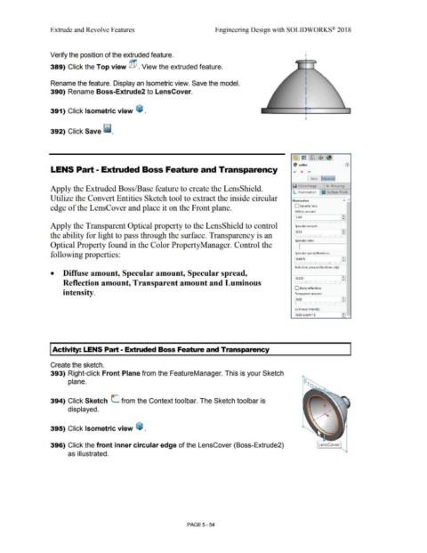
Create the sketch.
393) Right-click Front Plane from the FeatureManager. This is your Sketch
plane.
o-
394) Click Sketch L from the Context toolbar. The Sketch toolbar is
displayed.
395) Click Isometric view ~ .
396) Click the front inner circular edge of the LensCover (Boss-Extrude2) LensCover
as illustrated.
PAGE5 - 54