
Page 425 - Subyek Computer Aided Design - [David Planchard] Engineering Design with SOLIDWORKS
P. 425
Engineering Design with SOLIDWORKS® 2018 Extrude and Revolve Features
BULB Part - Revolved Base Feature
Create the new part, BULB. The BULB utilizes a solid Revolved Base feature.
The solid Revolved Base feature requires a:
• Sketch plane (Right Plane)
• Sketch profile (Lines)
• Axis of Revolution (Centerline)
• Angle of Rotation (360°)
Utilize the centerline to create a diameter dimension for the profile. The flange of the
BULB is located inside the Counterbore hole of the LENS. Align the bottom of the flange
with the Front Plane. The Front Plane mates against the Counterbore face.
I Activity: BULB Part - Revolved Base Feature
Create a New part.
408) Click New LJ from the Menu bar.
409) Click the MY-TEMPLATES tab.
Templates Tutorial Y-TEMPLATES
410) Double-click PART-IN-ANSI, [PART-MM-ISO]. !ID PART-~-ANSI
!ID PART-~-ANSI
~ PART-MM-ISO
Save the part. Enter name and description.
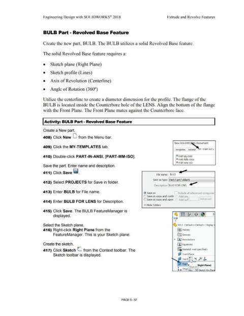
411) Click Save ii.
File name: BULB
Save as type: Part (*.prt;*.sldprt)
412) Select PROJECTS for Save in folder.
Description: BULB FOR LENS
413) Enter BULB for File name. @ Save as D Include all referenced componer
() Save as copy and contir Add pre l
IE) Save as copy and open Add suf1 I :Advanced]
414) Enter BULB FOR LENS for Description.
• Hide Folders
415) Click Save. The BULB FeatureManager is
displayed. ~ l~ llt8 1$ : >
~
Select the Sketch plane. ~ BULB (Default< <Default> _Display
416) Right-click Right Plane from the ~ I History
FeatureManager. This is your Sketch plane. ifl:J Sensors
• [A I Annotations
Create the sketch. ~ Equations
o-
417) Click Sketch L from the Context toolbar. The ~::a Material <not specified>
Sketch toolbar is displayed. a;J Front=Pl=an,--e ----1
(~ fe ~
: Top ~
· Righ .
, . Sk etc
h ght Plane)
L Ongi Ir.. i-~
PAGE5-57