
Page 429 - Subyek Computer Aided Design - [David Planchard] Engineering Design with SOLIDWORKS
P. 429
Engineering Design with SOLIDWORKS® 2018 Extrude and Revolve Features
461) Click Isometric view ~ .
462) Click Save ~ .
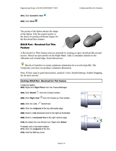
The points of the Spline dictate the shape
of the Spline. Edit the control points in
the sketch to produce different shapes for
the Revolved Boss feature.
BULB Part • Revolved Cut Thin
Feature
A Revolved Cut Thin feature removes material by rotating an open sketch profile around
an axis. Sketch an open profile on the Right Plane. Add a Coincident relation to the
silhouette and vertical edge. Insert dimensions.
, 1 /
-;Q~ Sketch a Centerline to create a diameter dimension for a revolved profile. The
Temporary axis does not produce a diameter dimension.
Note: If lines snap to grid intersections, uncheck Tools, Sketch Settings, Enable Snapping
for the next activity.
I Activity: BULB Part - Revolved Cut Thin Feature
Create the sketch.
463) Right-click Right Plane from the FeatureManager.
464) Click Sketch C from the Context toolbar.
465) Click Right view @ from the Heads-up View toolbar.
466) Click the Line / Sketch tool.
467) Click the midpoint of the top silhouette edge.
468) Sketch a line downward and to the right as illustrated.
469) Sketch a horizontal line to the right vertical edge.
470) De-select the Line Sketch tool. Right-click Select.
If needed, add a Coincident relation.
471) Click the endpoint of the line.
472) Hold the Ctrl key down.
PAGE5-61