
Page 426 - Subyek Computer Aided Design - [David Planchard] Engineering Design with SOLIDWORKS
P. 426
Extrude and Revolve Features Engineering Design with SOLIDWORKS® 2018
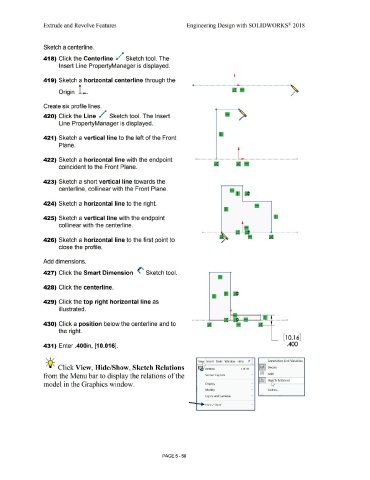
Sketch a centerline.
~p
418) Click the Centerline d ~ Sketch tool. The
Insert Line PropertyManager is displayed.
419) Sketch a horizontal centerline through the
Origin L. o---------·-·-·..__·-·-·-·-·-·-·---~
...
Create six profile lines.
420) Click the Line / Sketch tool. The Insert
Line PropertyManager is displayed.
421) Sketch a vertical line to the left of the Front
Plane.
422) Sketch a horizontal line with the endpoint
coincident to the Front Plane.
423) Sketch a short vertical line towards the
centerline, collinear with the Front Plane.
424) Sketch a horizontal line to the right.
425) Sketch a vertical line with the endpoint
collinear with the centerline.
---0---·-----·
426) Sketch a horizontal line to the first point to
close the profile.
Add dimensions.
427) Click the Smart Dimension (' Sketch tool.
428) Click the centerline.
429) Click the top right horizontal line as
illustrated.
---------- ----·
430) Click a position below the centerline and to
the right.
[ 10.16]
431) Enter .400in, [10.016]. .400
, 1,, ,,.
Vie~ Insert Tools Window Help Annotation Link Variables
-;Q~ Click View, Hide/Show, Sketch Relations I " I(©) I Decals
'
. ...... Redraw Ctrl+R
from the Menu bar to display the relations of the Screen Capture • 00 Grid
Ji Sk ,tch Relations
'
model in the Graphics window. Display • "u"
Modify • Bodies ...
Lights and Cameras • I
Hide/ Show •
PAGE5 - 58