
Page 427 - Subyek Computer Aided Design - [David Planchard] Engineering Design with SOLIDWORKS
P. 427
Engineering Design with SOLIDWORKS® 2018 Extrude and Revolve Features
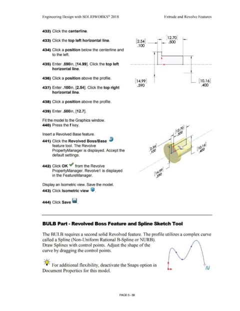
432) Click the centerline.
[12 70]
•
433) Click the top left horizontal line. [2.54] _ .500
.100
434) Click a position below the centerline and
to the left.
435) Enter .590in, [14.99]. Click the top left ·--·
horizontal line.
436) Click a position above the profile.
[14.99] [ 10.16]
.590 .400
437) Enter .100in, [2.54]. Click the top right
horizontal line.
438) Click a position above the profile.
439) Enter .500in, [12.7].
Fit the model to the Graphics window.
440) Press the f key.
10]
(1~()0 / • /
Insert a Revolved Base feature. ,5 • / •
/
441) Click the Revolved Boss/Base ~ / /
•
>
feature tool. The Revolve 16]
(1~
PropertyManager is displayed. Accept the
•
•
default settings.
/
•
/
•
/
•
442) Click OK ~ from the Revolve
PropertyManager. Revolve1 is displayed
in the FeatureManager.
Display an Isometric view. Save the model.
443) Click Isometric view ~ .
444) Click Save Ii.
BULB Part - Revolved Boss Feature and Spline Sketch Tool
The BULB requires a second solid Revolved feature. The profile utilizes a complex curve
called a Spline (Non-Uniform Rational B-Spline or NURB).
Draw Splines with control points. Adjust the shape of the
curve by dragging the control points.
, 1 /
-;Q~ For additional flexibility, deactivate the Snaps option in
'N
Document Properties for this model.
PAGE 5-59