
Page 432 - Subyek Computer Aided Design - [David Planchard] Engineering Design with SOLIDWORKS
P. 432
Extrude and Revolve Features Engineering Design with SOLIDWORKS® 2018
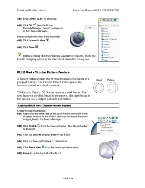
497) Enter .1 OOin, [2.54] for Distance.
498) Click OK ~ from the Dome ~ BULB (Default< <Default> _Disp
PropertyManager. Dome1 is displayed Face<1> ~ ] History
in the FeatureManager. ~ Sensors
• fA I Annotations
Display an Isometric view. Save the model. ~ Equations
o-
~:;; Material <not specified>
499) Click Isometric view ~ .
~ Front Plane
'
~ Top Plane
500) Click Save ii. ~ Right Plane
'
l... Origin
, 1/ • ~ Revolvel
-;Q~ Before creating sketches that use Geometric relations, check the • ~ Revolve2
• ~ Cut·Revolve-Thinl
Enable Snapping option in the Document Properties dialog box.
B Domel
BULB Part - Circular Pattern Feature
A Pattern feature creates one or more instances of a feature or a
Seed Pattern
group of features. The Circular Pattern feature places the
instances around an axis of revolution.
iv
The Circular Pattern 1>~<1 feature requires a seed feature. The
seed feature is the first feature in the pattern. The seed feature in
this section is a V-shaped Extruded Cut feature.
Activity: BULB Part - Circular Pattern Feature
Create the Seed Cut feature.
501) Right-click the front face of the Base feature, Revolve1 in the
Graphics window for the Sketch plane as illustrated. Revolve1
~ CR ~ l ~ ., ~· ~
is highlighted in the FeatureManager.
~ - ,~ fe>~ ®~
I Sketch pn Tools
502) Click Sketch (_ from the Context toolbar. The Sketch toolbar
Zoom/Pan/Rotate
is displayed.
Recent Commands
Face
503) Click the outside circular edge of the BULB.
504) Click the Convert Entities (El Sketch tool.
505) Click Front view ~ from the Heads-up View toolbar.
506) Zoom in on the top half of the BULB.
PAGE5-64