
Page 428 - Subyek Computer Aided Design - [David Planchard] Engineering Design with SOLIDWORKS
P. 428
Extrude and Revolve Features Engineering Design with SOLIDWORKS® 2018
I Activity: BULB Part - Revolved Boss Feature and Spline Sketch Tool
Create the sketch.
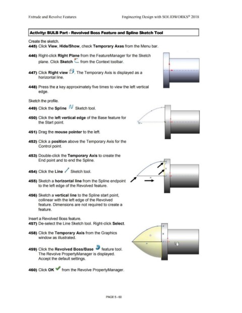
445) Click View, Hide/Show, check Temporary Axes from the Menu bar.
446) Right-click Right Plane from the FeatureManager for the Sketch
plane. Click Sketch L from the Context toolbar.
-·-·· -·-·-·-·-------·-·
447) Click Right view @ . The Temporary Axis is displayed as a
horizontal line.
448) Press the z key approximately five times to view the left vertical
edge.
Sketch the profile.
449) Click the Spline N Sketch tool.
450) Click the left vertical edge of the Base feature for
'
the Start point. ·' ro·~· ...................................... .
451) Drag the mouse pointer to the left.
452) Click a position above the Temporary Axis for the
Control point.
453) Double-click the Temporary Axis to create the
End point and to end the Spline.
/ ';
/"'
454) Click the Line / Sketch tool.
~-----Q-;t' - •, . - . - . - . - - - . - . - . - . - .
455) Sketch a horizontal line from the Spline endpoint
to the left edge of the Revolved feature.
456) Sketch a vertical line to the Spline start point,
collinear with the left edge of the Revolved
feature. Dimensions are not required to create a
feature.
Insert a Revolved Boss feature.
457) De-select the Line Sketch tool. Right-click Select.
458) Click the Temporary Axis from the Graphics
window as illustrated. •
459) Click the Revolved Boss/Base ~ feature tool.
The Revolve PropertyManager is displayed.
Accept the default settings.
460) Click OK ~ from the Revolve PropertyManager.
PAGE5-60