
Page 431 - Subyek Computer Aided Design - [David Planchard] Engineering Design with SOLIDWORKS
P. 431
Engineering Design with SOLIDWORKS® 2018 Extrude and Revolve Features
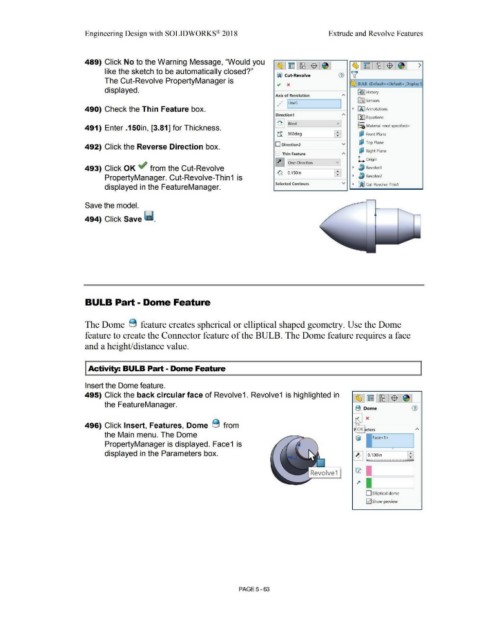
489) Click No to the Warning Message, "Would you
~ ~ - ~ $ ~ ~ ~ - ~ $ ~ >
like the sketch to be automatically closed?"
00 Cut-Revolve CV ~
The Cut-Revolve PropertyManager is
~ x :Q.1rJ BULB (Default<<Default> _Display S
displayed. ~I History
Axis of Revolution A
., faJ Sensors
,/ I Lines I
490) Check the Thin Feature box. • IA] Annotations
Direction1 "' ~ Equations
: ~ I !Blind vJ o-
~=il Material <not specified>
491) Enter .150in, [3.81] for Thickness.
tr 1360deg ~ di Front Plane
'
492) Click the Reverse Direction box. O Direction2 v ~ Top Plane
E:? Right Plane
Thin Feature
"'
~ One-Direction v L Origin
493) Click OK ~ from the Cut-Revolve • ~ Revolve1
0, :0.1 soin : I
PropertyManager. Cut-Revolve-Thin 1 is • lJ Revolve2
Selected Contours v • fiijJ Cut-Revolve-Thin1
displayed in the FeatureManager.
Save the model.
494) Click Save ii.
BULB Part - Dome Feature
The Dome 8 feature creates spherical or elliptical shaped geometry. Use the Dome
feature to create the Connector feature of the BULB. The Dome feature requires a face
and a height/distance value.
I Activity: BULB Part - Dome Feature
Insert the Dome feature.
495) Click the back circular face of Revolve1. Revolve1 is highlighted in (§,J ~ I ~ I $ I ~ I
the FeatureManager.
B Dome G)
496) Click Insert, Features, Dome 8 from
OK eters
the Main menu. The Dome
~ 1-1Face <-1 > ----,
PropertyManager is displayed. Face1 is
•
displayed in the Parameters box.
Revolve1 l:l:
D Elliptical dome
[21 Show preview
PAGE 5 - 63